BMW 7 Series: Replacing Rear Cross Member On Luggage Compartment Floor (Tail Panel Removed)
Read contents of BODY, GENERAL.
STRIP DOWN VEHICLE
Observe new procedure for bonding and riveting (REPAIR STAGE 2).
Following new body parts are required:
- End of luggage compartment floor
Following consumables are required:
MATERIAL CHART
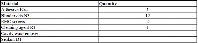
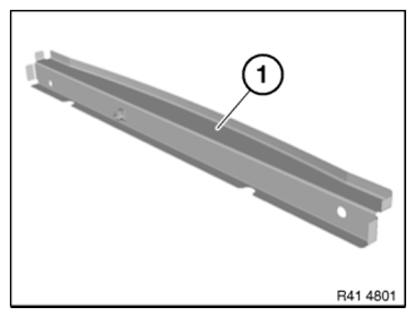
Fig. 349: Identifying End Of Luggage Compartment Floor
Removing cross member
Open welded connections in area (1) and remove cross member (2).
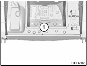
Fig. 350: Identifying Welded Connections Area
New part preparation
Adjust cross-member in combination with tail panel to fit and secure.
Drill 12 dia. 4.2 mm holes for blind rivets in area (1).
Remove new part again and deburr bore holes.
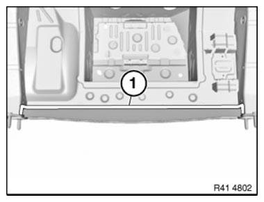
Fig. 351: Identifying Blind Rivets Area
Installing cross member
IMPORTANT: Do not grind new parts and body in area of bonding surfaces.
Clean all bonding surfaces on new part and on vehicle with cleaning agent R1.
Apply adhesive to bonding surfaces.
Install cross member and secure with blind rivets After adhesive has hardened: In the connection area of cross member to side member, fit 2 EMC SCREWS.
READ NEXT:
 Stripping Operations - Replacing Rear Left Side Panel
NOTE: Owing to the different engine variants and equipment specifications,
not all the
components are taken into consideration.
The following list basically represents the removal sequence.
Clamp o
Cover For Side Member At Rear (Rear Side Panel Removed)
Read contents of BODY, GENERAL.
Use only approved SPOT-WELDING APPARATUS for repairs.
The following new bodywork parts are required:
Cover, side member, rear (component is included on new side pan
SEE MORE:
Removing And Installing/Replacing Lower Left Or Right Cover (Wheel
Arch)
Necessary preliminary tasks
Remove UNDERBODY PROTECTION.
Release all screws (1).
Remove cover.
Replacement
From April 09 the snap fasteners are discontinued and replaced by a
conventional screw connection.
Fig. 103: Identifying Cover And Screws
REPLACING A BALL JOINT IN LEFT OR RIGHT SWINGING
Checking Camshaft Timing On Right Side (N63)
Notes
IMPORTANT: The timing can only be checked with special tool 11 9 900.
The timing may be misinterpreted if it is checked without special tool 11 9 900.
Cylinders 1-4:
Necessary preliminary work
Remove right CYLINDER HEAD COVER
Remove FAN COWL with electric fan
Remove BELT PULLEY for air co
