BMW 7 Series: Removing And Installing/Replacing Left Inlet Camshaft (N63)
Necessary preliminary work
(cylinder bank 5 to 8)
IMPORTANT: The intake camshaft must first be rotated in such a way that the camshaft is free from tension when the bearing caps are released (risk of damage).
- Remove LEFT CYLINDER HEAD COVER.
- Check TIMING.
- Remove LEFT INLET ADJUSTMENT UNIT.
IMPORTANT: No cam on the inlet camshaft is permitted to press directly onto a roller cam follower.
With cylinder no. 1 at 150º before firing TDC there is no piston in the TDC position.
Rotate left inlet camshaft at dihedron with a fork wrench (1) into a suitable position.
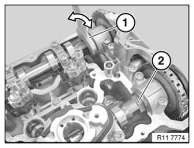
Fig. 248: Rotating Left Inlet Camshaft At Dihedron With Fork Wrench
Release bolts of camshaft bearings in sequence (10 to 1) in 1/2 turns.
Set down all bearing caps in a tidy and orderly fashion on special tool 11 4 480.
Intake camshaft
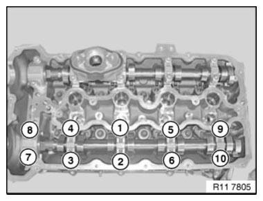
Fig. 249: Identifying Camshaft Bearings Bolts Releasing Sequence
IMPORTANT: Used rocker arms (1) may only be reused in the same position.
NOTE: Rocker arms (1) are freely accessible after inlet camshaft has been removed.
Do "not" remove rocker arm (1) on intake side.

Fig. 250: Identifying Rocker Arm
IMPORTANT: Plain compression rings (1) can easily break.
If necessary, replace plain compression rings (1).
Press compression ring (1) on one side into groove, pull up on other side and remove catch.
Carefully pull compression ring (1) apart and remove towards front.
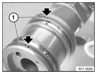
Fig. 251: Locating Compression Ring End
Ends of compression rings (1) point upwards.
Make sure compression rings (1) are engaged at ends.
NOTE: The intake camshaft of cylinder bank 5 to 8 is marked with "E 5-8".
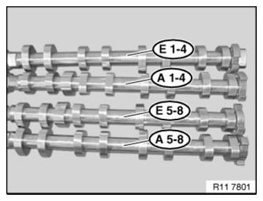
Fig. 252: Identifying Camshaft Of Cylinder Bank Mark
IMPORTANT: Rocker arms (1) slip slightly when inlet camshaft is fitted.
Make sure rocker arms (1) are secured as illustrated on hydraulic valve clearance compensating elements and on valves.
Align all rocker arms (1) straight.
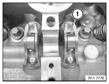
Fig. 253: Identifying Rocker Arm
Coat all bearing positions with engine oil.
Insert intake camshaft.
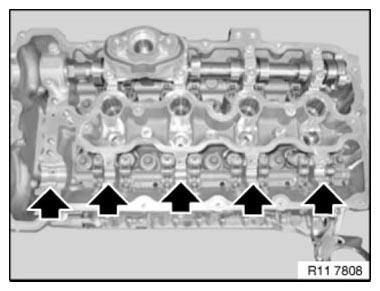
Fig. 254: Locating Bearing Positions
Insert inlet camshaft (1) so that cams point to side at cylinder 5 as shown in picture.
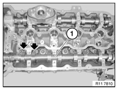
Fig. 255: Positioning Inlet Camshaft So That Cams Point To Side At Cylinder 5
IMPORTANT: Do not mix up the bearing caps of cylinders 1 to 4 and 5 to 8.
All bearing caps are coded and can only be installed in one position.
All bearing caps are marked:
L= Cylinders 1 - 4.
R= Cylinders 5 - 8.
E= Intake side
A= Exhaust side
1= designation from 1 to 5
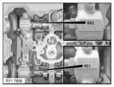
Fig. 256: Identifying Bearing Caps Mark
Insert all bolts.
Tighten down bolts in sequence (1 to 10) in 1/2 turns.
Tightening torque: 11 31 6AZ.
Tightening torque: 11 31 7AZ.

Fig. 257: Identifying Camshaft Bearings Bolts Tightening Sequence
Install INLET ADJUSTMENT UNITS.
Adjust VALVE TIMING.
Assemble engine.
READ NEXT:
 Removing And Installing/Replacing Right Inlet Camshaft (N63)
Necessary preliminary work
(cylinder bank 1 to 4)
IMPORTANT: The intake camshaft must first be rotated in such a way that
the camshaft is
free from tension when the bearing caps are released (risk of
Removing Hydraulic Chain Tensioner For Timing Chains On Left Side
(N63)
Notes
WARNING: Chain tensioner is pre-tensioned.
Release lock pin only in installed state.
Danger of injury!
IMPORTANT: Risk of damage!
The engine must not be cranked when the chain tensioner is rem
Removing Hydraulic Chain Tensioner For Timing Chains On Right Side
(N63)
Notes
WARNING: Chain tensioner is pre-tensioned.
Release lock pin only in installed state.
Danger of injury!
IMPORTANT: Risk of damage!
The engine must not be cranked when the chain tensioner is rem
SEE MORE:
Speed Limit Info
Speed Limit Info
Concept
Speed Limit Info shows the currently valid speed
limit in the instrument cluster and, if necessary,
the Head-up Display.
General information
The camera in the area of the interior mirror detects
traffic signs at the edge of the road as well
as overhead sign posts.
Traffic s
System Overview
Input/output Diagram, Steering Column Switch Cluster
Fig. 125: Steering Column Switch Cluster Input/Output Diagram
COMPONENTS DESCRIPTION CHART
Steering column stalk for turn-indicator/high-beam switch
Steering column switch cluster (SZL)
Steering column stalk wiper switch
Footwell module (FRM
