BMW 7 Series: Removing And Installing/Replacing Right Inlet Camshaft (N63)
Necessary preliminary work
(cylinder bank 1 to 4)
IMPORTANT: The intake camshaft must first be rotated in such a way that the camshaft is free from tension when the bearing caps are released (risk of damage).
- Remove right CYLINDER HEAD COVER.
- Check TIMING.
- Remove RIGHT INLET ADJUSTMENT UNIT.
IMPORTANT: No cam on the inlet camshaft is permitted to press directly onto a roller cam follower.
With cylinder no. 1 at 150º before firing TDC there is no piston in the TDC position.
Rotate right inlet camshaft (2) at dihedron with a fork wrench (1) into a suitable position.
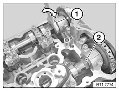
Fig. 258: Rotating Exhaust Camshaft At Dihedron With Fork Wrench Into
Suitable Position
NOTE: Illustration shows cyl. 5 to 8.
Release bolts of camshaft bearings in sequence (10 to 1) in 1/2 turns.
Set down all bearing caps in a tidy and orderly fashion on special tool 11 4 480.
Intake camshaft
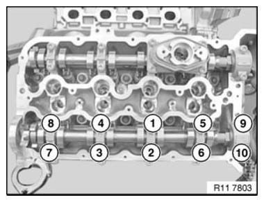
Fig. 259: Identifying Camshaft Bearings Bolts Releasing Sequence
IMPORTANT: Used rocker arms (1) may only be reused in the same position.
NOTE: Rocker arms (1) are freely accessible after inlet camshaft has been removed.
Do "not" remove rocker arm (1) on intake side.
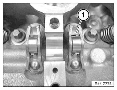
Fig. 260: Identifying Rocker Arm
IMPORTANT: Plain compression rings (1) can easily break.
If necessary, replace plain compression rings (1).
Press compression ring (1) on one side into groove, pull up on other side and remove catch.
Carefully pull compression ring (1) apart and remove towards front.
Ends of compression rings (1) point upwards.
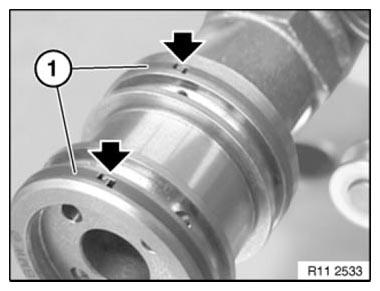
Fig. 261: Locating Compression Ring End
Make sure compression rings (1) are engaged at ends.
NOTE: The intake camshaft of cylinder bank 5 to 8 is marked with "E 5-8".
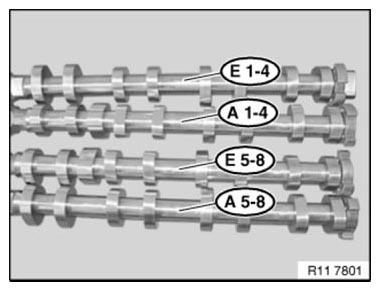
Fig. 262: Identifying Camshaft Of Cylinder Bank Mark
IMPORTANT: Rocker arms (1) slip slightly when inlet camshaft is fitted.
Make sure rocker arms (1) are secured as illustrated on hydraulic valve clearance compensating elements and on valves.
Align all rocker arms (1) straight.

Fig. 263: Identifying Rocker Arm
Coat all bearing positions with engine oil.
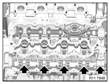
Fig. 264: Locating Bearing Positions
Insert intake camshaft.
Insert inlet camshaft (1) so that cams point to side at cylinder 1 as shown in picture.
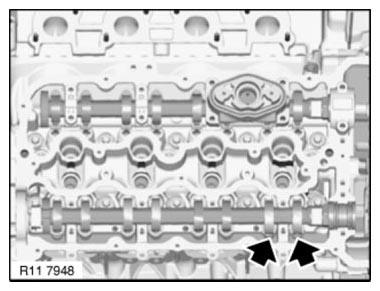
Fig. 265: Positioning Inlet Camshaft So That Cams Point To Side At Cylinder 1
IMPORTANT: Do not mix up the bearing caps of cylinders 1 to 4 and 5 to 8.
All bearing caps are coded and can only be installed in one position.
All bearing caps are marked with letters and numbers:
L= Cylinder bank 1-4.
R= Cylinder bank 5-8.
E= Intake side
A= Exhaust side
1= designation, bearing point, from 1 to 5
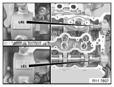
Fig. 266: Identifying Bearing Caps Marks
Insert all bolts.
Tighten down bolts in sequence (1 to 10) in 1/2 turns.
Tightening torque: 11 31 6 AZ.
Tightening torque: 11 31 7 AZ.

Fig. 267: Identifying Camshaft Bearings Bolts Tightening Sequence
Install INLET ADJUSTMENT UNITS.
Adjust VALVE TIMING.
Assemble engine.
READ NEXT:
 Removing Hydraulic Chain Tensioner For Timing Chains On Left Side
(N63)
Removing Hydraulic Chain Tensioner For Timing Chains On Left Side
(N63)
Notes
WARNING: Chain tensioner is pre-tensioned.
Release lock pin only in installed state.
Danger of injury!
IMPORTANT: Risk of damage!
The engine must not be cranked when the chain tensioner is rem
Removing Hydraulic Chain Tensioner For Timing Chains On Right Side
(N63)
Notes
WARNING: Chain tensioner is pre-tensioned.
Release lock pin only in installed state.
Danger of injury!
IMPORTANT: Risk of damage!
The engine must not be cranked when the chain tensioner is rem
Replacing Both Timing Chains (N63)
Notes
WARNING: Burning hazard! Wear gloves.
Necessary preliminary work
Remove lower TIMING CASE COVER
To facilitate removal and installation of timing chains, turn engine
over with special tool 0
SEE MORE:
Straightening Aluminium Components In Structure
Reshaping or heating extruded sections and cast parts is not
permitted!
Failure to comply with this requirement would have the following
results:
In the case of reshaping, weld seams (E52) or glued connections (E60, E61,
E63, E64) tear in the
surrounding area.
In the case of reshaping, t
Removing And Installing/Replacing Right Exhaust Manifold (N63)
WARNING: Risk of burning!
Only perform this repair work on an engine that has cooled down.
Necessary preliminary work
Remove left TURBOCHARGER.
Remove right TURBOCHARGER.
Remove ALTERNATOR (not F04).
Release screws (1).
Tightening torque 18 31 4AZ.
Fig. 59: Identifying Screws
Release screws (
