BMW 7 Series: Replacing Both Timing Chains (N63)
Notes
WARNING: Burning hazard! Wear gloves.
Necessary preliminary work
- Remove lower TIMING CASE COVER
- To facilitate removal and installation of timing chains, turn engine over with special tool 00 2 300.
Timing drive, cylinders 1 to 4
Remove guide rail (5) from bearing bolt.
Remove timing chain (3) with tensioning rail (4) from bearing bolt.
Timing drive, cylinders 5 to 8
Remove guide rail (1) from bearing bolt.
Remove timing chain (2) with tensioning rail (6) from bearing bolt.
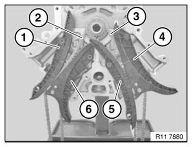
Fig. 278: Identifying Guide Rail, Timing Chain And Tensioning Rail
Timing drive, cylinders 1 to 4
Release bearing bolts (2) with a suitable tool.
Tightening torque: 11 31 1AZ.
Timing drive, cylinders 5 to 8
Release bearing bolts (1).
Tightening torque: 11 31 2AZ.
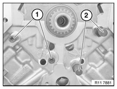
Fig. 279: Identifying Bearing Bolts
Attach special tools 11 2 001 and 11 2 002 to the crankshaft.
Insert special tool 11 2 007 and remove sprocket wheel with special tool 11 2 003.
Installation note: Check sprocket wheels for wear, replace if necessary.
Heat sprocket wheel to 60ºC.
WARNING: Burning hazard! Wear gloves.
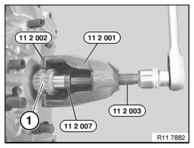
Fig. 280: Removing Sprocket Wheel With Special Tool 11 2 003
Installation note: Make sure Woodruff key (1) is installed in correct position in crankshaft (2).
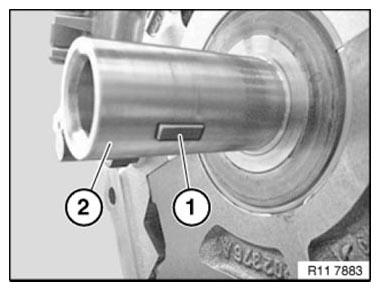
Fig. 281: Identifying Woodruff Key Installed In Correct Position In
Crankshaft
Installation note: Maintain tension of timing chains when installing timing case cover.
Observe sparking protection on timing case cover.
Make sure timing chain (1) is correctly installed when placing it in guide rail (3).
Assemble engine.
READ NEXT:
 Rocker Arm With Bearing Mount
REMOVING AND INSTALLING/RENEWING ROCKER ARMS ON RIGHT SIDE (N63)
Necessary preliminary work
(cylinder bank 1 to 4)
Remove INLET AND EXHAUST ADJUSTMENT UNIT on right side.
Remove right INLET CAMSHAF
Valves With Springs
REMOVING AND INSTALLING/REPLACING ALL VALVES (N63)
Necessary preliminary work
Remove LEFT CYLINDER HEAD.
Remove RIGHT CYLINDER HEAD.
Remove camshafts.
Mount cylinder head (1) on special tool 11
Replacing All Valve Springs (N63)
Necessary preliminary work
Remove LEFT CYLINDER HEAD.
Remove RIGHT CYLINDER HEAD.
Remove camshafts.
Mount cylinder head (1) on special tool 11 9 000.
Fig. 292: Mounting Cylinder Head On Special
SEE MORE:
Repairing Airbag Cables
IMPORTANT: Only repair those cables which show visible signs of damage. In
the event of
visible damage, make sure there is only one cable repair in effect after the
repair work. If no visible damage can be identified, the entire cable must be
replaced. When carrying out repairs to the airbag wiring
Exterior mirrors
General information
The mirror on the front passenger side is more
curved than the driver's side mirror.
The mirror setting is stored for the driver profile
currently in use. When a driver profile is selected,
the stored position is called up automatically.
The current exterior mirror position can
