BMW 7 Series: Rocker Arm With Bearing Mount
REMOVING AND INSTALLING/RENEWING ROCKER ARMS ON RIGHT SIDE (N63)
Necessary preliminary work
(cylinder bank 1 to 4)
- Remove INLET AND EXHAUST ADJUSTMENT UNIT on right side.
- Remove right INLET CAMSHAFT.
- Remove right EXHAUST CAMSHAFT.
IMPORTANT: Used rocker arms (1) may only be reused in the same position.
Tolerance classes are not required.
Remove rocker arm (1) and set down in neat order in special tool 11 4 480.
Install rocker arm (1).
Align all rocker arms (1) straight.
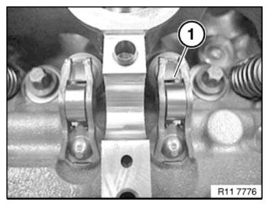
Fig. 282: Identifying Rocker Arm
Assemble engine.
REMOVING AND INSTALLING/REPLACING ALL ROCKER ARMS ON LEFT SIDE (N63)
Necessary preliminary work
(cylinder bank 5 to 8)
- Remove LEFT INLET CAMSHAFT.
- Remove left EXHAUST CAMSHAFT.
IMPORTANT: Used rocker arms (1) may only be reused in the same position.
Tolerance classes are not required.
Remove rocker arm (1) and set down in neat order in special tool 11 4 480.
Install rocker arm (1).
Align all rocker arms (1) straight.
.png)
Fig. 283: Identifying Rocker Arm
Assemble engine.
READ NEXT:
 Valves With Springs
REMOVING AND INSTALLING/REPLACING ALL VALVES (N63)
Necessary preliminary work
Remove LEFT CYLINDER HEAD.
Remove RIGHT CYLINDER HEAD.
Remove camshafts.
Mount cylinder head (1) on special tool 11
Replacing All Valve Springs (N63)
Necessary preliminary work
Remove LEFT CYLINDER HEAD.
Remove RIGHT CYLINDER HEAD.
Remove camshafts.
Mount cylinder head (1) on special tool 11 9 000.
Fig. 292: Mounting Cylinder Head On Special
Replacing All Valve Stem Seals (N63)
Notes
IMPORTANT: Risk of damage to sealing lip on valve stem seal.
Fit new valve stem seals only when all valves have been installed.
Necessary preliminary work
Remove all VALVE SPRINGS.
Press spe
SEE MORE:
DTC Index
N63
SELF-DIAGNOSTICS DTC
SELF-DIAGNOSTICS DIAGNOSTIC TROUBLE CODE (DTC) LIST
DTC INDEX - THEORY & OPERATION (N63)
Theory & Operation - 750i, 750Li (N63)
DIAGNOSTIC TROUBLE CODE INDEX
DIAGNOSTIC TROUBLE CODE INDEX (THEORY & OPERATION N63)
750i & 750Li
BUZZERS
Removing Ball Pivot
NOTE: Remove gas spring, refer to REMOVING GAS SPRING.
NOTE: The following text describes how to remove the ball pivot from the
hinge
retaining bracket on the rear lid as an example. Proceed in the same way for the
other ball pivots.
Make sure the attachments are reinstalled in the correct sequenc
