BMW 7 Series: Removing Hydraulic Chain Tensioner For Timing Chains On Right Side (N63)
Notes
WARNING: Chain tensioner is pre-tensioned.
Release lock pin only in installed state.
Danger of injury!
IMPORTANT: Risk of damage! The engine must not be cranked when the chain tensioner is removed.
The timing chain may jump.
Necessary preliminary work
- Remove TIMING CASE COVER at top right
Crank engine back at central bolt (1) against direction of engine rotation by approx. 180º.
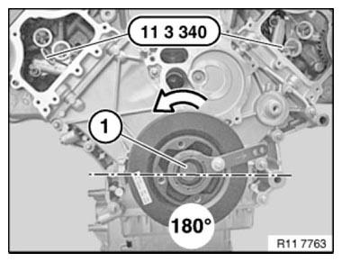
Fig. 273: Cranking Engine Back At Central Bolt Against Direction Of Engine
Rotation By Approx. 180º
IMPORTANT: The timing chain on the chain tensioner becomes the tight end on cranking back.
Do not crank engine without chain tensioner or special tool 11 9 900.
Piston (1) of chain tensioner must be pressed in against oil pressure in housing (see arrow).
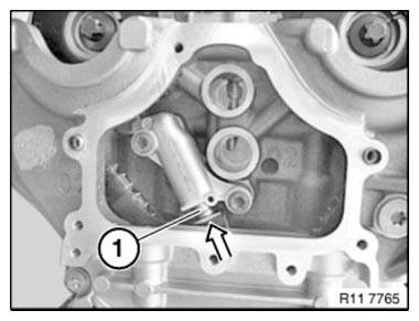
Fig. 274: Identifying Piston Of Chain Tensioner Pressed In Against Oil
Pressure In Housing
If the chain tensioner piston is retracted over its full length, a 3.5 mm drill bit or a suitable lock pin must be positioned.
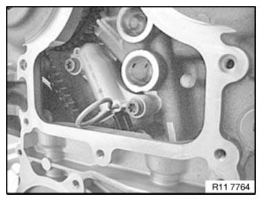
Fig. 275: Identifying Chain Tensioner Piston Retracted Over Its Full Length
Release screws (1).
Tightening torque 11 31 5AZ.
Remove chain tensioner (2).
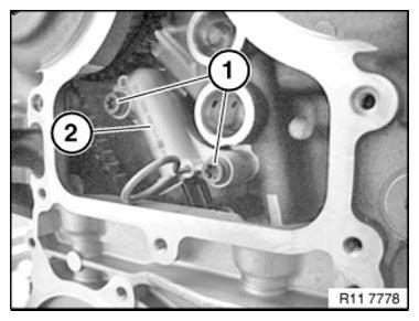
Fig. 276: Identifying Chain Tensioner And Screws
IMPORTANT: Danger of injury! Chain tensioner is under high preload force.
Chain tensioner arrangement:
- Piston
- Expansion element
- Compression spring
- Housing
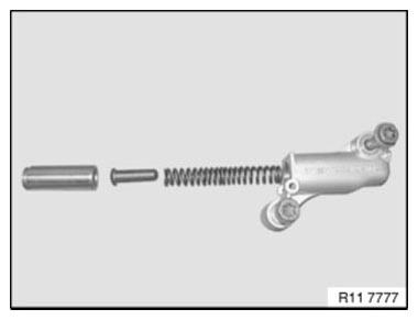
Fig. 277: Identifying Chain Tensioner Arrangement
Installation note:
Replace all gaskets and sealing rings
Assemble engine.
READ NEXT:
 Replacing Both Timing Chains (N63)
Notes
WARNING: Burning hazard! Wear gloves.
Necessary preliminary work
Remove lower TIMING CASE COVER
To facilitate removal and installation of timing chains, turn engine
over with special tool 0
Rocker Arm With Bearing Mount
REMOVING AND INSTALLING/RENEWING ROCKER ARMS ON RIGHT SIDE (N63)
Necessary preliminary work
(cylinder bank 1 to 4)
Remove INLET AND EXHAUST ADJUSTMENT UNIT on right side.
Remove right INLET CAMSHAF
Valves With Springs
REMOVING AND INSTALLING/REPLACING ALL VALVES (N63)
Necessary preliminary work
Remove LEFT CYLINDER HEAD.
Remove RIGHT CYLINDER HEAD.
Remove camshafts.
Mount cylinder head (1) on special tool 11
SEE MORE:
Lowering/Raising Rear Axle Support
Notes
IMPORTANT: Before lowering rear axle support:
Observe SAFETY INSTRUCTIONS on raising the vehicle.
In order to avoid damage to lifting platform, perform weight compensation on
vehicle.
Load luggage compartment with sand bags.
Necessary preliminary tasks
Remove REAR WHEELS
F03 only: Remove
Using this Owner's Manual
Orientation
The fastest way to find information on a particular
topic is by using the index.
An initial overview of the vehicle is provided in
the first chapter.
Validity of the Owner's Manual
Production of the vehicle
At the time of production at the plant, the printed
Owner's Manual is the most c
