BMW 7 Series: Replacing Front Left Wheel Arch
Note the special vehicle identification number procedure when replacing the front right wheel arch (order the new body part with the vehicle identification number, if necessary)! These instructions are only applicable the first time the wheel arch is replaced! Repeated replacement is only permitted after consultation with and release by BMW. Should you have any questions, please contact the country-specific Hotline.
If the wheel arch has not yet been replaced, this can be recognized from the punch rivets (1) fitted at the factory.
If replacing the wheel arch, replace the punch rivets with blind rivets (2).
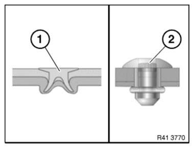
Fig. 223: Identifying Punch And Blind Rivets
Observe procedure of REPAIR STAGE 3.
Read contents of BODY, GENERAL.
Strip down vehicle.
Steel-aluminium composite construction is used on the vehicle. Observe specific procedure.
Spot-weld bonding is used on this vehicle. Observe specific PROCEDURE.
Use only approved SPOT-WELDING EQUIPMENT for repairs! Place vehicle on straightening bench.
Following new body parts are required:
- Wheel arch, front
- Connection, side frame, rear
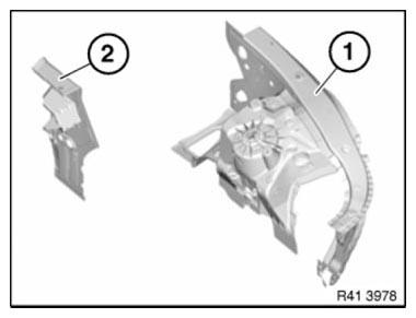
Fig. 224: Identifying Connection, Side Frame, Rear And Wheel Arch, Front
Open spot-weld bonded joints in area (1).
OPEN WELDED CONNECTIONS IN AREAS (2).
ROUGHLY CUT SIDE FRAME CONNECTION (3) ALONG LINES (4).
REMOVE SIDE FRAME CONNECTION (3).
REPLACE CAVITY SEALING.
Installation note: MAG weld new part in areas (4).
To do so, apply 10 mm long fillet welds at spacing of 15 mm.
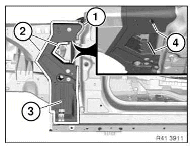
Fig. 225: Identifying Spot-Welded Adhesive Joints Area And Side Frame
Connection
Drill out rivet connections in area (1).
Open BONDED CONNECTION in area (1).
Installation note: Use 6 N2 RIVETS in area (1).
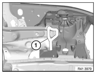
Fig. 226: Identifying Rivets Area
View from above: Open welded connections in areas (1) to (3).
NOTE: Cut out component roughly and open welded connections from inside.
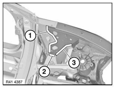
Fig. 227: Identifying Welded Connections Areas
View from below: Open welded connections in area (1).
Drill out rivet connections in area (2).
Open bonded connection in area (2).
Installation note: Use 10 rivets N2 in area (2).
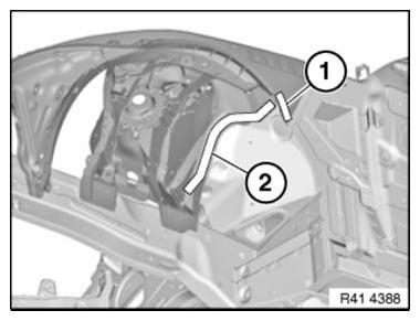
Fig. 228: Identifying Rivet Connections And Welded Connections Area
Open welded connections in area (1).
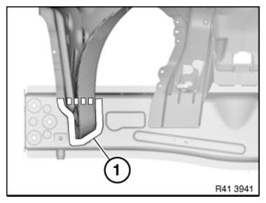
Fig. 229: Identifying Welded Connections Area
Drill out rivet connections in areas (1) and (2).
Open bonded connections in areas (1) and (2).
Installation note:
Adjust new part to fit with alignment bracket or universal mount.
CARRY OVER HOLE PATTERN from engine support to new part in areas (1).
Carry over new rivet holes from engine support to wheel arch in area (2).
Use 4 N2 rivets in area (2).
Glue new part with ADHESIVE K1.
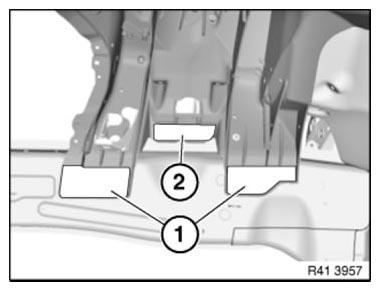
Fig. 230: Identifying Rivet Holes Drill Areas
IMPORTANT: To avoid contact corrosion, do not grind the new wheel arch part in the area of the BONDING SURFACES.
Grind bonding surfaces on engine support blank.
Clean bonding surfaces with CLEANING AGENT R1 !
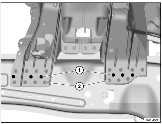
Fig. 231: Identifying Rivet Positions
Installation note: Additional rivet positions are required for strength reasons.
- Additional rivet positions (black, number 6)
- Previous rivet positions (grey, number 15)
Drill additional rivet holes as shown in picture.
Use 21 N 2 rivets.
Glue new part with adhesive K1.
Installation note: MAG-weld new part in area (1).
To do so, apply 2 fillet welds at distance of approx. 20 mm. Length of fillet welds approx. 10 mm.
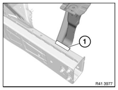
Fig. 232: Identifying New Component MAG-Welding Area
READ NEXT:
 Replacing Outer Section Of Left Or Right Rear Wheel Housing (Side
Panel Removed)
Replacing Outer Section Of Left Or Right Rear Wheel Housing (Side
Panel Removed)
Read contents of BODY, GENERAL.
Spot-weld bonding is used on this vehicle. Observe specific procedure.
Remove or cover those vehicle components in the repair area which are
susceptible to heat or d
Replacing Rear Left Outer Wheel Arch Section (Rear Side Panel
Removed)
Read contents of BODY, GENERAL.
Remove or cover those vehicle components in the repair area which are
susceptible to heat or dust.
Use only approved SPOT-WELDING APPARATUS for repairs.
Following n
Stamping Vehicle Identification Number (Needle Stamping Unit)
Read and comply with GENERAL INFORMATION.
The needle stamping system 360 - VRM - BMW is required to stamp the vehicle
identification number.
Order number: 81 43 2 155 736
Sourcing reference:
BMW
SEE MORE:
Removing And Installing/Replacing Sensor For Fuel Gauge
Recycling
Fuel escapes when fuel lines are detached. Have a suitable collecting
container ready.
Catch and dispose of escaping fuel.
Observe country-specific waste-disposal regulations.
IMPORTANT: Ensure adequate ventilation in the place of work!
Avoid skin contact (wear gloves)!
Ensure absolute
Release Transmission Lock Electronically
For various tasks, it is necessary to unlock and lock the parking lock.
Before unlocking the parking lock, secure the vehicle against rolling away.
Emergency release is only possible if the engine does not start and the
starter turns over.
If an emergency release needs to be performed although
