BMW 7 Series: Replacing Crankshaft (N63)
Notes
IMPORTANT: Weight of crankshaft is approx. 20 kg.
Risk of injury from sharp edge of housing.
Necessary preliminary work
- Remove ENGINE
- Mount engine on assembly stand
- Remove cylinder head
- Remove HUB FOR VIBRATION DAMPER
- Removing LOWER TIMING CASE COVER
- Removing oil pan
- Remove OIL PUMP
- Removing PISTON
- Remove FLYWHEEL
- Remove radial shaft seals
- Remove TIMING CHAINS
Installation note: Layout of main bearing caps.
All numbers must be read from the cylinder bank (5 to 8) (see arrows).
.png)
Fig. 117: Locating Main Bearing Caps Numbers
Main bearing caps (1 to 5) opposite the output end on the timing chain drive.
.png)
Fig. 118: Identifying Main Bearing Caps Numbers
Release oil pump spacer bolts (1) with special tool 13 5 020.
.png)
Fig. 119: Removing Oil Pump Spacer Bolts With Special Tool 13 5 020
Release main bearing taper screw connection (1).
Release oil pump spacer pins (2).
.png)
Fig. 120: Identifying Main Bearing Taper Screw Connection And Oil Pump Spacer
Pins
Release all threaded support sleeves (1).
.png)
Fig. 121: Removing Threaded Support Sleeves
Release collar bolts (M8) in sequence 10 to 1.
.png)
Fig. 122: Identifying Collar Bolts (M8) Releasing Sequence
Release collar bolts (M11) in sequence 10 to 1.
Remove main bearing caps 1 to 5.
IMPORTANT: Remove crankshaft with a 2nd person, weight approx. 25 kg.
Lift out crankshaft and set down safely (secure against turning).
.png)
Fig. 123: Identifying Collar Bolts (M11) Releasing Sequence
Release screw for oil nozzle (1).
Tightening torque: 11 11 8 AZ.
.png)
Fig. 124: Identifying Oil Nozzle
Installation note: Check oil nozzle (1) for clear passage with compressed air.
Observe fastening on oil nozzle.
.png)
Fig. 125: Locating Fastening On Oil Nozzle
Installation note: Observe fastening in crankcase.
.png)
Fig. 126: Locating Fastening In Crankcase
Replace CRANKSHAFT MAIN BEARING SHELLS.
Installation note: Observe arrangement of main bearing caps.
All numbers must be read from the cylinder bank (5 to 8) (see arrows).
.png)
Fig. 127: Locating Main Bearing Caps Numbers
Main bearing caps (1) is opposite the output end on the timing chain drive.
Turn back all threaded support sleeves hand-tight.
Installation note: Coat all bearing positions with engine oil.
IMPORTANT: Install crankshaft with a 2nd person, weight approx. 25 kg.
.png)
Fig. 128: Identifying Main Bearing Caps Numbers
Install crankshaft.
Fit bearing caps (1 to 5).
Set down bearing caps positioned from 1 to 5.
Insert all collar bolts (M11) hand-tight.
Secure collar bolts (M11) in sequence (1 to 10).
.png)
Fig. 129: Identifying Collar Bolts (M11) Tightening Sequence
Installation note: For a better overview of the screw connection quality, mark the head of all collar bolts after joining with a line (1) using an oil-proof marker pen.
Check angle tightening.
.png)
Fig. 130: Identifying Collar Bolts Head Mark
Secure collar bolt (1) with special tool 00 9 120.
Tightening torque: 11 11 1AZ.
.png)
Fig. 131: Securing Collar Bolt With Special Tool 00 9 120
Insert all collar bolts (M8) hand-tight.
Secure collar bolts (M8) in sequence (1 to 10).
.png)
Fig. 132: Identifying Collar Bolts (M8) Tightening Sequence
Installation note: For a better overview of the screw connection quality, mark the head of all collar bolts after joining with a line (1) using an oil-proof marker pen.
Check angle tightening.
.png)
Fig. 133: Identifying Collar Bolts Head Mark
Secure collar bolt (1) with special tool 00 9 120.
.png)
Fig. 134: Securing Collar Bolt With Special Tool 00 9 120
Secure all threaded support sleeves (1) with special tool 11 4 350.
Tightening torque: 11 11 3 AZ.
.png)
Fig. 135: Securing All Threaded Support Sleeves With Special Tool 11 4 350
Secure main bearing taper screw connection (1).
Tightening torque: 11 11 4 AZ.
.png)
Fig. 136: Identifying Main Bearing Taper Screw Connection And Oil Pump Spacer
Pins
Check crankshaft COEFFICIENT OF FRICTION.
Determine crankshaft breakaway torque with special tool 00 2 010.
Rotate crankshaft at central bolt using special tool 00 2 010.
If the breakaway torque is too high, it will be necessary to correct the bearing clearance.
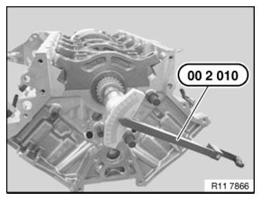
Fig. 137: Checking Crankshaft Breakaway Torque With Special Tool 00 2 010
Secure special tool 11 6 252 to crankcase with magnetic base.
Slide crankshaft in direction of arrow forwards as far as it will go.
Set special tool 11 6 251 to zero.
Slide crankshaft (1) in direction of arrow towards rear and determine value.
Check axial play.
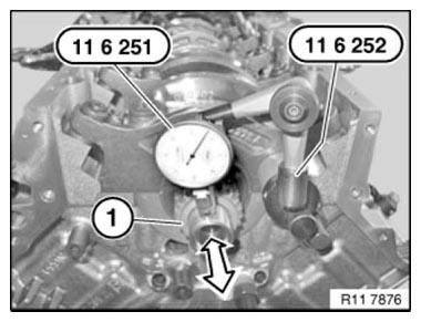
Fig. 138: Checking Axial Play
Assemble engine.
READ NEXT:
 Flywheel
REMOVING AND INSTALLING/REPLACING FLYWHEEL (N63)
Necessary preliminary tasks
Remove AUTOMATIC TRANSMISSION
Remove manual transmission
Remove clutch
Secure flywheel (1) with special tool 11 9 260.
Vibration Damper
REMOVING AND INSTALLING/RENEWING VIBRATION DAMPER (N63)
Necessary preliminary work
Remove FAN COWL
Remove A/C compressor DRIVE BELT
Remove alternator DRIVE BELT
Remove belt pulley for A/C system
Connecting Rod With Bearing
REPLACING ALL CONNECTING ROD BEARINGS (N63)
Notes
IMPORTANT: Note grinding stages on crankshaft.
Necessary preliminary work
Removing all PISTONS
Install new connecting rod bearing shells.
Install
SEE MORE:
Clutch
Clutch With Driving Disc
Precautionary Measures On Vehicles With Active Pedestrian
Protection System
WARNING: Danger to life!
Triggering the active pedestrian protection system while the engine
compartment lid is open may cause serious
injury by the retaining hooks.
Use protection systems when car
Removing And Installing/Renewing Dynamic Drive In The Wheel Arch
Notes
WARNING: DANGER OF POISONING if oil is ingested/absorbed through the
skin!
RISK OF INJURY if oil comes into contact with eyes and skin!
IMPORTANT: Adhere to the utmost cleanliness. Do not allow any dirt to
enter the hydraulic
system.
Do not draw off hydraulic fluid (risk of contamination).
