BMW 7 Series: Flywheel
REMOVING AND INSTALLING/REPLACING FLYWHEEL (N63)
Necessary preliminary tasks
- Remove AUTOMATIC TRANSMISSION
- Remove manual transmission
- Remove clutch
Secure flywheel (1) with special tool 11 9 260.
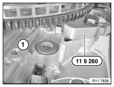
Fig. 139: Securing Flywheel With Special Tool 11 9 260
Release flywheel screws in area (1).
Remove flywheel (2).
Installation: Clean threads on flywheel screws in crankshaft.
Flywheel (2) is secured with an alignment pin.
Fit flywheel (2).
Fit new flywheel screws
Tightening torque 11 22 1AZ.
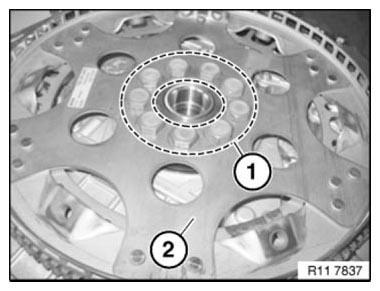
Fig. 140: Identifying Flywheel Screws
REMOVING AND INSTALLING/REPLACING FLYWHEEL (TRANSMISSION REMOVED - N63)
Notes
Secure flywheel (1) with special tool 11 9 260.

Fig. 141: Securing Flywheel With Special Tool 11 9 260
Release flywheel screws in area (1).
Remove flywheel (2).
Installation: Clean threads on flywheel screws in crankshaft.
Flywheel (2) is secured with an alignment pin.
Fit flywheel (2).
Fit new flywheel screws
Tightening torque 11 22 1AZ.

Fig. 142: Identifying Flywheel Screws
REPLACING ROLLER BEARING FOR DUAL-MASS FLYWHEEL (N63)
Notes
NOTE: FLYWHEEL removed!
Using hydraulic press (1) and special tool 21 2 051, press roller bearing out of dual-mass flywheel downwards on engine side.
IMPORTANT: Risk of damage: Roller bearing must not be driven out.
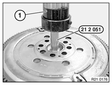
Fig. 143: Pressing Roller Bearing Out Of Dual-Mass Flywheel Downwards On
Engine Side
Push roller bearing (2) onto special tool 21 2 052.
Using hydraulic press (1), press roller bearing into dual-mass flywheel as far as it will go on clutch side.
IMPORTANT: Risk of damage: Observe press-in instruction:
- Roller bearing must not be driven in.
- Roller bearing mounting force/travel monitored:
Min. 2000 N 1 mm before end of pressing in.
Max. 15, 000 N during entire press-in procedure.
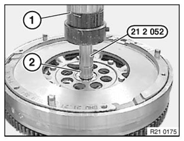
Fig. 144: Pressing Roller Bearing Into Dual-Mass Flywheel
READ NEXT:
 Vibration Damper
REMOVING AND INSTALLING/RENEWING VIBRATION DAMPER (N63)
Necessary preliminary work
Remove FAN COWL
Remove A/C compressor DRIVE BELT
Remove alternator DRIVE BELT
Remove belt pulley for A/C system
Connecting Rod With Bearing
REPLACING ALL CONNECTING ROD BEARINGS (N63)
Notes
IMPORTANT: Note grinding stages on crankshaft.
Necessary preliminary work
Removing all PISTONS
Install new connecting rod bearing shells.
Install
SEE MORE:
Refueling
Vehicle features and
options
This chapter describes all standard, country-specific
and optional features offered with the series.
It also describes features and functions that are
not necessarily available in your vehicle, e.g., due
to the selected options or country versions. This
also applies to
Safety Regulations For Handling Components With Gas Generators
It is essential to comply with the regulations as specified in the law
relating to the use of explosives when
working on airbag units and seat belt tensioners.
Airbags, seat belt tensioners etc. are pyrotechnically objects. Pyrotechnical
objects are assigned to different
danger classes on the basi
