BMW 7 Series: Vibration Damper
REMOVING AND INSTALLING/RENEWING VIBRATION DAMPER (N63)
Necessary preliminary work
- Remove FAN COWL
- Remove A/C compressor DRIVE BELT
- Remove alternator DRIVE BELT
- Remove belt pulley for A/C system
Release screw (1).
Tightening torque 11 28 1AZ.
Remove belt tensioner with idler pulley (2).
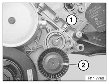
Fig. 145: Identifying Screw And Idler Pulley
Secure special tool 11 8 090 with three screws (1) to vibration damper.
Secure special tool 11 8 090 with belt tensioner bolt (2) to timing case cover.
Tightening torque 11 28 1AZ.
NOTE: A 3/4 inch tool is needed to release the central bolt.
Release central bolt on vibration damper.
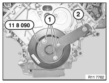
Fig. 146: Securing Special Tool 11 8 090 With Belt Tensioner Bolt To Timing
Case Cover
Secure central bolt with special tool 00 9 140 or 11 3 460.
Position special tool 11 3 460 on special tool 11 8 090.
Adjust special tool 11 9 453 on special tool 11 9 454 using clamping screw to 0º on scale.
Tightening torque 11 23 1AZ.
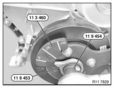
Fig. 147: Adjusting Special Tool 11 9 453 On Special Tool 11 9 454 Using
Clamping Screw To 0º On Scale
Assemble engine.
READ NEXT:
 Connecting Rod With Bearing
REPLACING ALL CONNECTING ROD BEARINGS (N63)
Notes
IMPORTANT: Note grinding stages on crankshaft.
Necessary preliminary work
Removing all PISTONS
Install new connecting rod bearing shells.
Install
Removing And Installing/Replacing All Pistons (N63) Up To 3/2011
Notes
WARNING: Protective goggles must be worn when working on the gudgeon
pin circlip.
IMPORTANT: If pistons and connecting rods are reused, they must be
reinstalled in the same
places.
Piston and
SEE MORE:
Removing And Installing/Replacing Feed Line (N63)
Notes
WARNING: Clamp off BATTERY NEGATIVE TERMINAL (risk of fire due to
shortcircuiting
on removal).
Electric fuel pump starts up automatically when door is opened!
Carry out installation work on fuel system only with coolant temperature
below 40ºC.
Wear protective goggles.
Wear protective glove
Rear seats
General information
The seat adjustment switches are located on the
center armrest of the rear seats.
If the safety switch is pressed, the seats cannot
be adjusted.
Additional information:
Safety switch
Safety information
Warning
There is a risk of jamming when folding down
the center armrest in
