BMW 7 Series: Removing And Installing/Replacing All Pistons (N63) Up To 3/2011
Notes
WARNING: Protective goggles must be worn when working on the gudgeon pin circlip.
IMPORTANT: If pistons and connecting rods are reused, they must be reinstalled in the same places.
Piston and piston pin are matched to each other and can only be replaced as a pair.
Conrod and conrod bearing cap are cracked.
Identification is effected by means of identical pairing letters on the connecting rod big end.
Mixing up the components will result in engine damage.
Conrod bearings must always be replaced.
Necessary preliminary tasks
- Remove ENGINE
- Install engine on assembly stand
- Remove LEFT CYLINDER HEAD
- Remove RIGHT CYLINDER HEAD
- Removing oil pan
- Remove OIL PUMP
Unscrew connecting rod bearing cap.
NOTE: Connecting rods and connecting rod bearing caps are denoted with the same pairing letters.
The stamped dates are always arranged in opposite directions.
Set down conrod bearing caps in order.
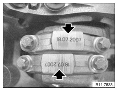
Fig. 154: Locating Connecting Rod Bearing Caps Stamped Dates
NOTE: To install and remove the conrods, it is essential for the crankshaft to be exactly in alignment with the cylinder bore (see dashed line).
Position crankshaft at central bolt.
Insert special tool 11 8 152 into conrod.
Screw special tool 11 5 440 into conrod with bolt (1).
Remove conrod with piston from cylinder head side.
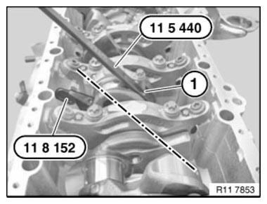
Fig. 155: Removing Conrod With Piston From Cylinder Head Side
IMPORTANT: Piston and piston bolts are paired and must not be fitted individually.
Lift out retaining ring and press out piston pin.

Fig. 156: Removing Retaining Ring From Piston
If necessary, replace connecting rods.
NOTE: The conrods can also be replaced individually.
The gudgeon pin must be able to be pressed through the liner by hand with little force and must not display any significant play.
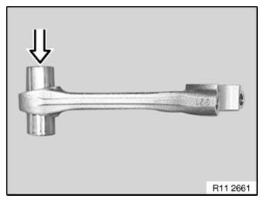
Fig. 157: Installing Gudgeon Pin
Prior to installation, measure piston installation clearance: Measure piston diameter with micrometer at measuring point A from lower edge of piston and offset by 90º to piston pin axis.
Refer to MEASURING POINT A.
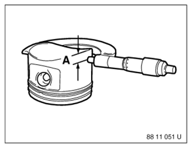
Fig. 158: Measuring Piston Diameter
Adjust micrometer to cylinder bore of engine block. Set internal calliper on micrometer to zero. Measure bottom, center and top of cylinder bore in direction of travel and direction of engine rotation.
Refer to:
- DIAMETER OF CYLINDER BORE
- PISTON INSTALLATION CLEARANCE
- TOTAL PERMISSIBLE WEAR CLEARANCE
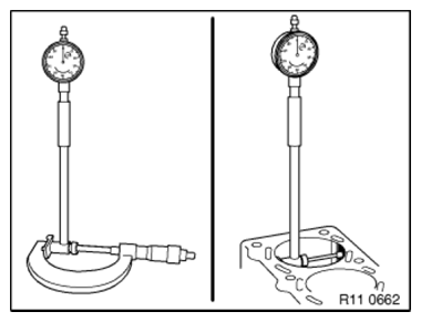
Fig. 159: Checking Diameter Of Cylinder Bore
IMPORTANT: The conrods of cylinder banks 1 to 4 and 5 to 8 are mounted to the pistons differently.
NOTE: The pistons and conrods of cylinders 1 to 8 are identical.
Arrow on piston crown (cyl. 1 to 4) points upwards, bolt connection on conrod points at an angle to right.
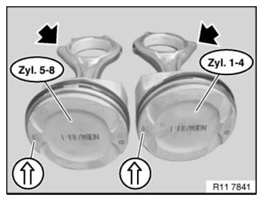
Fig. 160: Identifying Arrow On Piston Crown
Arrow on piston crown (cyl. 5 to 8) points upwards, bolt connection on conrod points at an angle to left.
NOTE: For purposes of clarity, pistons are shown removed.
The conrods are correctly mounted on the piston when the bolt connections on the conrods are parallel to each other (see arrow).
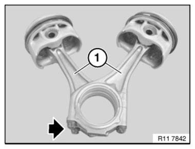
Fig. 161: Identifying Bolt Connections On Conrods Are Parallel To Each Other
Install retaining ring.
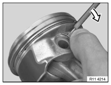
Fig. 162: Installing Retaining Ring
Installation: Piston circlip (1) is correctly installed when the opening points upwards.
See illustration.
It must still be possible for the piston pin to moved easily.
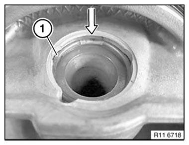
Fig. 163: Locating Piston Circlip
Insert special tools 11 8 151 and 11 8 152 into conrod.
INSTALL CONNECTING ROD BEARING.
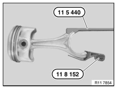
Fig. 164: Inserting Special Tools 11 8 151 And 11 8 152 Into Conrod
Lightly coat pistons and piston rings with oil.
Offset the contact points of the piston rings by approx. 120º to each other but do not position above the piston pin boss.
NOTE: Illustration shows S85.
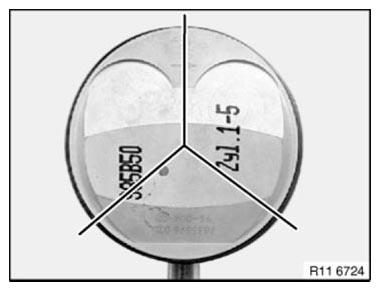
Fig. 165: Identifying Piston Rings Offset Contact Points
Keep piston rods compressed with special tool 11 7 280.
Install piston so that arrow points to camshaft drive.
IMPORTANT: Danger of piston ring failure.
Press in piston only with finger force (do not knock in!).
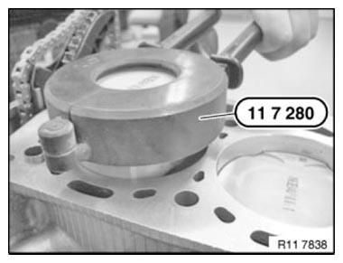
Fig. 166: Compressing Piston Rods With Special Tool 11 7 280
IMPORTANT: Danger of piston ring failure.
Press in piston (1) only with finger force (do not knock in!).
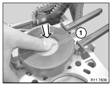
Fig. 167: Pressing In Piston Only With Finger Force
The direction arrow on the piston crown must point to the camshaft drive (direction of travel towards front).
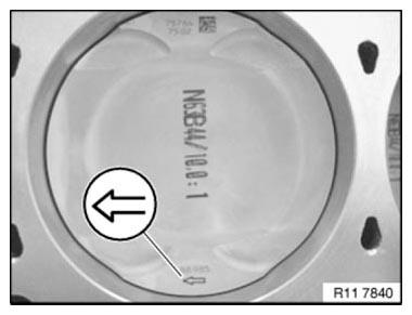
Fig. 168: Identifying Arrow Direction On Piston Crown Must Point To Camshaft
Drive (Direction Of
Travel Towards Front)
Attach crankshaft journal to connecting rod.
Remove special tools 11 5 440 and 11 8 152.

Fig. 169: Attaching Crankshaft Journal To Connecting Rod
NOTE: For purposes of clarity, the pairing letters (1) are shown on the removed conrod.
IMPORTANT: Conrods and conrod bearing caps are denoted with the same pairing letters (1), do not mix them up.
Fit bearing cap so that pairing letters match up.
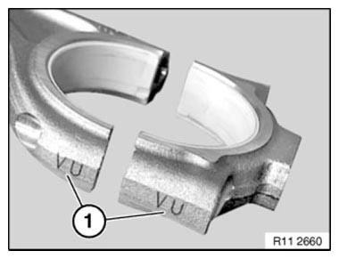
Fig. 170: Identifying Conrods And Conrod Bearing Caps Pairing Letters
Apply light coat of oil to connecting-rod bearing shells.
Fit bearing cap so that pairing letters match up.
Install new conrod bolts.
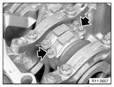
Fig. 171: Locating Conrod Bolts
Tighten down connecting rod bolts (1) with special tool 00 9 120.
Tightening torque 11 24 1 AZ.
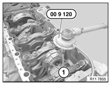
Fig. 172: Tightening Down Connecting Rod Bolts With Special Tool 00 9 120
Assemble engine.
READ NEXT:
 Removing And Installing/Replacing All Pistons (N63) From 3/2011
Notes
WARNING: Protective goggles must be worn when working on the gudgeon
pin
circlip.
IMPORTANT: If pistons and connecting rods are reused, they must be
reinstalled in the same
places.
Piston and
V-Ribbed Belt W.Tens./Deflect
REPLACING A/C COMPRESSOR DRIVE BELT WITH BELT TENSIONER (N63)
IMPORTANT: Risk of damage!
Release screws (1) on vibration absorber only if removal position is adjusted.
If contaminated with hydraulic
SEE MORE:
Body - Operating Fluids
1.0 SEALING COMPOUNDS
Seam Sealer, Sikaflex 221 may be used to seal adjoining sheet metal parts
which create creaking noises due to
interactive contact. High-adhesion, polyurethane-based, black-colored.
Sikaflex 221 Sealer
BMW Part No. 81 22 9 407 533
Other sealants for body panels are found in Gr
Removing And Installing/Replacing Right High Pressure Pump (N63)
WARNING: Observe warning on cylinder head cover.
Disconnect NEGATIVE BATTERY TERMINAL (risk of fire due to short
circuit on removal).
Electric fuel pump starts up automatically when door is opened!
Carry out installation work on fuel system only with coolant temperature
below 40ºC.
IMPORTANT: Wea
