BMW 7 Series: Removing And Installing/Replacing All Pistons (N63) From 3/2011
Notes
WARNING: Protective goggles must be worn when working on the gudgeon pin circlip.
IMPORTANT: If pistons and connecting rods are reused, they must be reinstalled in the same places.
Piston and piston pin are matched to each other and can only be replaced as a pair.
Conrod and conrod bearing cap are cracked.
Identification is effected by means of identical pairing letters on the connecting rod big end.
Mixing up the components will result in engine damage.
Conrod bearings must always be replaced.
Necessary preliminary tasks
- Fully remove front axle together with engine.
- Remove ENGINE from front axle.
- Install engine on assembly stand.
- Remove LEFT CYLINDER HEAD.
- Remove RIGHT CYLINDER HEAD.
- Removing oil sump.
- Remove OIL PUMP.
To release the connecting rod bolts (1), the crankshaft (2) must be moved to a suitable position.
Release connecting rod bolts (1).
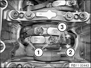
Fig. 173: Identifying Connecting Rod Bolts And Crankshaft
Screw the special tool 2 249 164 (assembly tool) into the connecting rod.
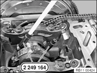
Fig. 174: Identifying Special Tool 2 249 164 Secured To Connecting Rod
NOTE: For installation and dismantling of the connecting rods, it is essential for the crankshaft to be exactly in alignment with the cylinder bore.
Position crankshaft at central bolt.
Insert special tool 11 8 152 into conrod.
Press out the connecting rod and piston with special tool 22 49 164 towards the cylinder head side.
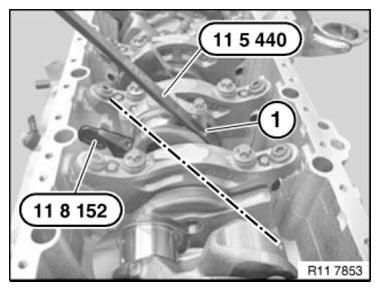
Fig. 175: Removing Conrod With Piston From Cylinder Head Side
IMPORTANT: Pistons and gudgeon pins are paired and must not be fitted individually.
Lift out circlip and press out piston pin.
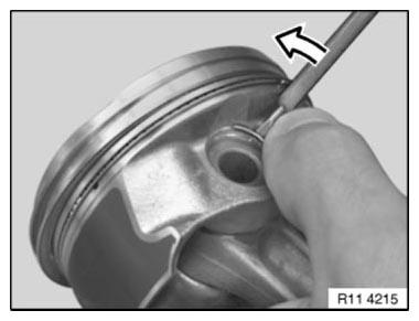
Fig. 176: Removing Retaining Ring From Piston
If necessary, replace connecting rods.
NOTE: The connecting rod can also be replaced individually.
The gudgeon pin must be able to be pressed through the bush by hand with little force and must not display any significant play.
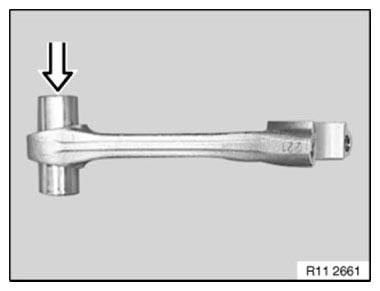
Fig. 177: Installing Gudgeon Pin
Prior to installation, measure piston installation clearance: Measure piston diameter with micrometer at measuring point A from lower edge of piston and offset at 90º to the axis of the gudgeon pin.
Refer to MEASURING POINT A.
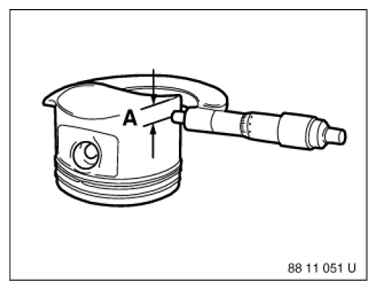
Fig. 178: Measuring Piston Diameter
Adjust micrometer to cylinder bore of engine block. Set internal calliper on micrometer to zero. Measure bottom, center and top of cylinder bore in direction of travel and direction of engine rotation.
Refer to:
- DIAMETER OF CYLINDER BORE
- PISTON INSTALLATION CLEARANCE
- TOTAL PERMISSIBLE WEAR CLEARANCE
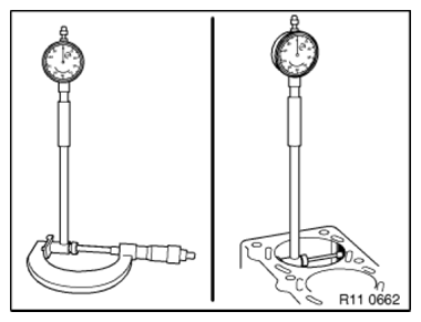
Fig. 179: Checking Diameter Of Cylinder Bore
Installation note: Piston circlip (1) is correctly installed when the opening points upwards.
See illustration.
It must still be possible for the gudgeon pin to be moved easily.
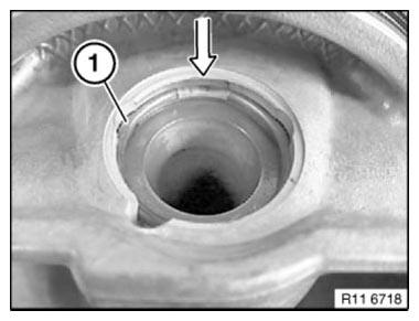
Fig. 180: Locating Piston Circlip
Insert the special tools 22 49 164 (assembly tool) into the connecting rod.
Install CONNECTING ROD BEARING.
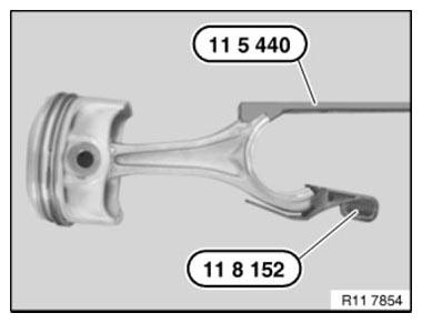
Fig. 181: Inserting Special Tools 11 8 151 And 11 8 152 Into Conrod
Lightly coat pistons and piston rings with oil.
Offset the contact points of the piston rings by approx. 120º to each other but do not position above the piston pin boss.
NOTE: Illustration shows S85.
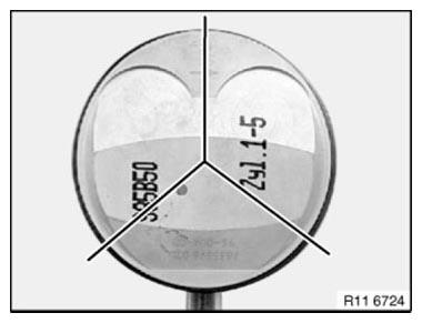
Fig. 182: Identifying Piston Rings Offset Contact Points
Keep piston rods compressed with special tool 11 7 280.
Install piston so that arrow points to camshaft drive.
IMPORTANT: Risk of piston ring breakage.
Press in piston only with finger force (do not knock in!).
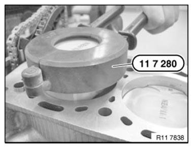
Fig. 183: Compressing Piston Rods With Special Tool 11 7 280
The direction arrow on the piston crown must point to the camshaft drive (direction of travel towards front).
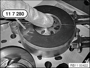
Fig. 184: Identifying Piston Crown Direction
Connect the crankshaft journal to connecting rod.
Remove special tools 22 49 164.
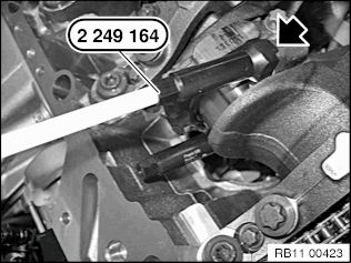
Fig. 185: Connecting Crankshaft Journal And Connecting Rod And Removing
Special Tools 22 49 164
NOTE: For purposes of clarity, the pairing letters (1) are shown on the removed connecting rod.
IMPORTANT: Connecting rods and connecting rod bearing caps are denoted with the same pairing letters (1), do not mix them up.
Fit bearing cap so that pairing letters match up.
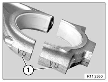
Fig. 186: Identifying Conrods And Conrod Bearing Caps Pairing Letters
Apply light coat of oil to connecting rod bearing shells.
Fit bearing cap so that pairing letters match up.
Install new connecting rod bolts.
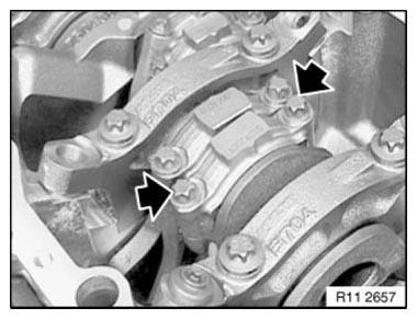
Fig. 187: Locating Conrod Bolts
Tighten down connecting rod bolts (1) with special tool 00 9 120.
Tightening torque 11 24 1 AZ.
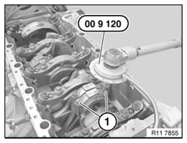
Fig. 188: Tightening Down Connecting Rod Bolts With Special Tool 00 9 120
READ NEXT:
 V-Ribbed Belt W.Tens./Deflect
REPLACING A/C COMPRESSOR DRIVE BELT WITH BELT TENSIONER (N63)
IMPORTANT: Risk of damage!
Release screws (1) on vibration absorber only if removal position is adjusted.
If contaminated with hydraulic
Adjusting Camshaft Timing On Left Side (N63)
Notes
IMPORTANT: Release central bolts on adjuster only with special tool 11 9
890.
Risk of damage to timing drive.
If special tool 11 9 890 can not be fitted, it is necessary when releasing the
ce
SEE MORE:
Wiper system- Windshield washer system
Safety information
Warning
The washer fluid can freeze onto the window at
low temperatures and obstruct the view. There
is a risk of accident. Only use the washer systems,
if the washer fluid cannot freeze. Use
washer fluid with antifreeze, if needed.
NOTICE
When the washer fluid reservoir is empt
Stamping Vehicle Identification Number (Needle Stamping Unit)
Read and comply with GENERAL INFORMATION.
The needle stamping system 360 - VRM - BMW is required to stamp the vehicle
identification number.
Order number: 81 43 2 155 736
Sourcing reference:
BMW Workshop Equipment Catalogue.
Fig. 243: Identifying Display, Mains Adapter, Needle Stamping Unit,
