BMW 7 Series: Adjusting Camshaft Timing On Left Side (N63)
Notes
IMPORTANT: Release central bolts on adjuster only with special tool 11 9 890.
Risk of damage to timing drive.
If special tool 11 9 890 can not be fitted, it is necessary when releasing the central bolt to grip the hexagon head of the respective camshaft.
(cylinder bank 5 to 8)
Necessary preliminary work
- Remove LEFT GEAR CASE COVER
- CHECK CAMSHAFT TIMING ON LEFT SIDE
Get set of special tools 11 9 890 ready for securing camshafts.
NOTE: Special tool 11 9 891 Knurled screw.
Special tool 11 9 892 Press-down bar.
Special tool 11 9 893 Gap gauge for intake and exhaust camshafts.
Special tool 11 9 894 spacer.
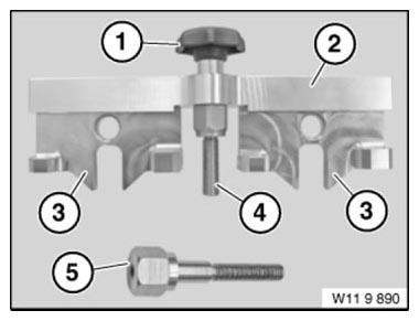
Fig. 194: Identifying Set Of Special Tools 11 9 890
IMPORTANT: If special tool 11 9 890 can not be fitted, it is necessary when releasing the central bolt to grip the hexagon head of the respective camshaft.
Release central bolts (1 and 2) of intake and exhaust camshaft adjusters.
Installation note: Replace central bolts after releasing.

Fig. 195: Identifying Central Bolts Of Intake And Exhaust Camshaft Adjusters
IMPORTANT: Check whether head of central bolt (1) is greased (see arrow).
If no grease can be seen on the bolt head of central bolt (1), the ADJUSTER must be replaced for safety reasons.
Installation note: Coat contact surface of new central bolt (1) with copper paste.
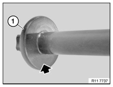
Fig. 196: Checking Head Of Central Bolt
Position special tool 11 9 893 on intake camshaft and exhaust camshaft.
The special tool 11 9 893 must rest without a gap on cylinder head; if necessary, adjust camshaft at hexagon heads.
Screw special tool 11 9 894 into cylinder head.
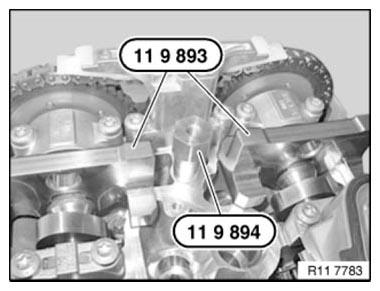
Fig. 197: Positioning Special Tool 11 9 893 On Intake Camshaft And Exhaust
Camshaft
Position special tool 11 9 892 on special tool 11 9 893.
Both special tools11 9 891 are secured with special tool 11 9 893.
NOTE: Tighten down special tool 11 9 891 by hand.

Fig. 198: Positioning Special Tool 11 9 892 On Special Tool 11 9 893
Secure central bolt (1) of intake camshaft adjuster with special tool 00 9 120.
Secure central bolt (2) of exhaust camshaft adjuster with special tool 00 9 120.
Tightening torque: 11 36 1AZ.
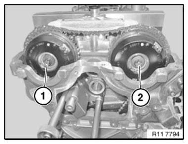
Fig. 199: Identifying Central Bolts Of Intake And Exhaust Camshaft Adjusters
Remove special tools 11 9 190 and 11 8 570.
Crank engine at central bolt twice in direction of engine rotation until engine returns to 150º before cylinder no. 1 firing TDC position.
Secure vibration damper with special tool 11 9 190 at 150º before cylinder no. 1 firing TDC position 1.
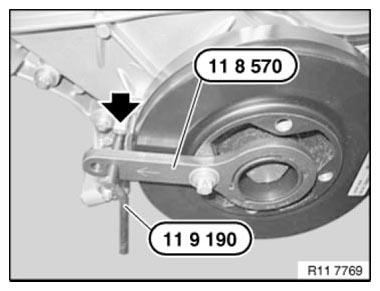
Fig. 200: Securing Vibration Damper With Special Tool 11 9 190
Place special tool11 9 893 on the exhaust camshaft and check timing adjustment.
NOTE: Timing is correctly adjusted when special tool 11 9 893 rests without a gap on cylinder head.
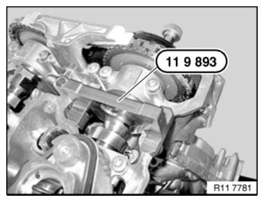
Fig. 201: Identifying Special Tool 11 9 893 On Exhaust Camshaft
Fit special tool 11 9 893 on intake camshaft and check timing adjustment.
NOTE: Timing is correctly adjusted when special tool 11 9 893 rests without a gap on cylinder head.
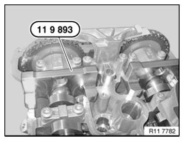
Fig. 202: Identifying Special Tool 11 9 893 On Intake Camshaft
Remove all special tools.
Assemble engine.
READ NEXT:
 Adjusting Camshaft Timing On Right Side (N63)
Notes
IMPORTANT: Release central bolts on adjuster only with special tool 11 9
890.
Risk of damage to timing drive.
If special tool 11 9 890 can not be fitted, it is necessary when releasing the
ce
Checking Camshaft Timing On Left Side (N63)
Notes
IMPORTANT: The timing can only be checked with special tool 11 9 900.
The timing may be misinterpreted if it is checked without special tool 11 9 900.
Cylinders 5-8:
Necessary preliminary work
Checking Camshaft Timing On Right Side (N63)
Notes
IMPORTANT: The timing can only be checked with special tool 11 9 900.
The timing may be misinterpreted if it is checked without special tool 11 9 900.
Cylinders 1-4:
Necessary preliminary work
SEE MORE:
Removing And Replacing The Catalytic Converter Cylinder 1-4 (N63)
WARNING: Risk of burning!
Only perform this repair work on an engine that has cooled down.
Necessary preliminary work
Remove ACOUSTIC COVER.
REMOVE BOTH INTAKE SILENCER HOUSINGS.
Remove EXHAUST SYSTEM.
Remove both control sensors.
Remove both monitoring sensors.
Picture shows the left side,
Removing And Installing/Renewing USB Interface Connecting Socket
Necessary preliminary work:
Remove SWITCH FOR FRONT PASSENGER AIRBAG DEACTIVATION
NOTE: Open glove box
Disconnect plug connection (1).
Unlock retaining clips (2) on left/right.
Press out USB interface connecting socket (3) in direction of arrow.
Installation note:
Retaining clips (2) must not
