BMW 7 Series: Checking Camshaft Timing On Left Side (N63)
Notes
IMPORTANT: The timing can only be checked with special tool 11 9 900.
The timing may be misinterpreted if it is checked without special tool 11 9 900.
Cylinders 5-8:
Necessary preliminary work
- Remove left CYLINDER HEAD COVER
- Remove FAN COWL with electric fan
- Remove BELT PULLEY for air conditioning system
- Remove left CHAIN TENSIONER
Mount special tool 11 9 900 at position of chain tensioner.
Preload hexagon socket screw with special tool 00 9 250 to 0.6 Nm.
NOTE: Graphic corresponds to cylinders 1-4.
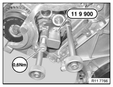
Fig. 212: Preloading Hexagon Socket Screw With Special Tool 00 9 250 To 0.6
Nm
NOTE: Marking (MP = Mounting Position) is important for installing special tool 11 8 570.
MP = 150º before cylinder no. 1 firing TDC position
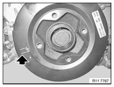
Fig. 213: Identifying Mounting Position Of Special Tool 11 8 570
Position special tool 11 8 570 with dihedron on vibration damper in such a way that it can be secured with bolt (1) at the MP marking.
NOTE: Setting groove on crankcase, see arrow.
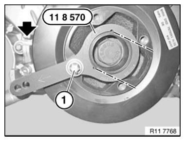
Fig. 214: Positioning Special Tool 11 8 570 With Dihedron On Vibration Damper
Crank engine at central bolt.
Secure vibration damper with special tools 11 8 570 and 11 9 190 at 150º before cylinder no. 1 firing TDC position.
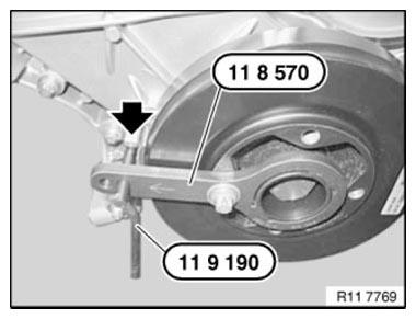
Fig. 215: Securing Vibration Damper With Special Tool 11 9 190
With cylinder no. 1 at 150º before firing TDC position, cams on exhaust camshaft (A) at cylinder no. 5 point at an angle to the left.
Cams on inlet camshaft (E) point at an angle downwards.
NOTE: For purposes of clarity, the graphic shows the inlet and exhaust adjustment units removed.
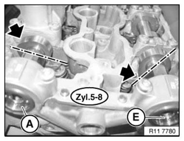
Fig. 216: Identifying Cams On Inlet Camshaft Point At An Angle Downwards
IMPORTANT: When the engine is shut down, the inlet and exhaust adjustment units are normally locked in their initial position.
The situation may arise in some individual cases where this initial position is not reached and the camshaft can continue to be rotated in the adjustment range of the camshaft adjuster.
In order to avoid incorrect timing adjustment, it is essential to check the locking of the camshaft adjuster and if necessary perform locking by rotating the camshafts.
Checking locking of intake and exhaust camshaft adjusters in initial setting: Gripping hexagon head (2) of camshafts with a fork wrench (1), carefully try to rotate camshafts against direction of rotation.
The intake and exhaust camshaft adjusters are locked in the initial setting when the camshafts are non-positively connected to the adjusters.
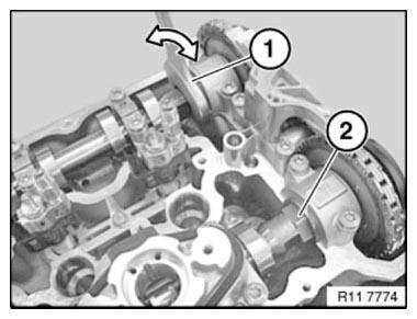
Fig. 217: Gripping Hexagon Head Of Camshafts With Fork Wrench
IMPORTANT: If the intake or exhaust camshaft adjusters of the camshafts "cannot" be locked as described, the adjuster is faulty and must be replaced.
Place special tool 11 9 893 on the exhaust camshaft and check timing adjustment.
NOTE: Timing is correctly adjusted when special tool 11 9 893 rests without a gap on cylinder head.
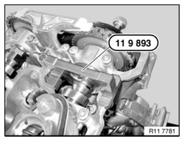
Fig. 218: Identifying Special Tool 11 9 893 On Exhaust Camshaft
Fit special tool 11 9 893 on intake camshaft and check timing adjustment.
NOTE: Timing is correctly adjusted when special tool 11 9 893 rests without a gap on cylinder head.
If necessary, adjust camshaft TIMING on left side.
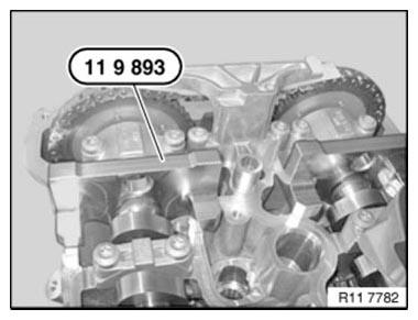
Fig. 219: Identifying Special Tool 11 9 893 On Intake Camshaft
Remove all special tools.
Assemble engine.
READ NEXT:
 Checking Camshaft Timing On Right Side (N63)
Notes
IMPORTANT: The timing can only be checked with special tool 11 9 900.
The timing may be misinterpreted if it is checked without special tool 11 9 900.
Cylinders 1-4:
Necessary preliminary work
Removing And Installing/Renewing Right Exhaust Camshaft (N63)
Notes
Cylinders 1-4:
IMPORTANT: Risk of damage!
The exhaust camshaft must first be rotated in such a way that the camshaft is
free from tension when the bearing caps are released.
Necessary preliminar
Removing And Installing/Renewing Rocker Arms On Right Side (N63)
Necessary preliminary work
(cylinder bank 1 to 4)
Remove INLET AND EXHAUST ADJUSTMENT UNIT on right side.
Remove right INLET CAMSHAFT.
Remove right EXHAUST CAMSHAFT.
IMPORTANT: Used rocker arms (
SEE MORE:
Opening Adhesive Bonds
1. Opening spot-weld bonds
OPEN WELD SPOTS.
WARNING: Extract vapors and gases.
Use personal protective clothing/equipment.
Heat connecting flange with a hot-air blower. Heat components to max. 250ºC
object temperature.
Release connection flange with chisel.
Remove adhesive residue from connecti
Replacing Audio Unit
IMPORTANT: Read and comply with notes on protection against electrostatic
damage (ESD
PROTECTION).
IMPORTANT: Use of supplied gloves is mandatory
Carry out installation in a dust-free workshop area only.
To avoid damage, do not touch or dirty the display field.
Necessary preliminary work:
Remove
