BMW 7 Series: Removing And Installing/Renewing Rocker Arms On Right Side (N63)
Necessary preliminary work
(cylinder bank 1 to 4)
- Remove INLET AND EXHAUST ADJUSTMENT UNIT on right side.
- Remove right INLET CAMSHAFT.
- Remove right EXHAUST CAMSHAFT.
IMPORTANT: Used rocker arms (1) may only be reused in the same position.
Tolerance classes are not required.
Remove rocker arm (1) and set down in neat order in special tool 11 4 480.
Install rocker arm (1).
Align all rocker arms (1) straight.

Fig. 237: Identifying Rocker Arm
Assemble engine.
REMOVING AND INSTALLING/REPLACING ALL ROCKER ARMS ON LEFT SIDE (N63)
Necessary preliminary work
(cylinder bank 5 to 8)
- Remove LEFT INLET CAMSHAFT.
- Remove left EXHAUST CAMSHAFT.
IMPORTANT: Used rocker arms (1) may only be reused in the same position.
Tolerance classes are not required.
Remove rocker arm (1) and set down in neat order in special tool 11 4 480.
Install rocker arm (1).
Align all rocker arms (1) straight.
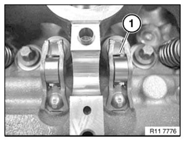
Fig. 238: Identifying Rocker Arm
Assemble engine.
REMOVING AND INSTALLING/REPLACING LEFT EXHAUST CAMSHAFT (N63)
Necessary preliminary work
(cylinder bank 5 to 8)
IMPORTANT: The exhaust camshaft must first be rotated in such a way that the camshaft is free from tension when the bearing caps are released risk of damage.
- Remove LEFT CYLINDER HEAD COVER.
- Check TIMING.
- Remove LEFT INLET ADJUSTMENT UNIT.
IMPORTANT: No cam on the exhaust camshaft is permitted to press directly onto a roller cam follower.
With cylinder no. 1 at 150º before firing TDC there is no piston in the TDC position.
Rotate exhaust camshaft (2) at dihedron with a fork wrench into a suitable position.
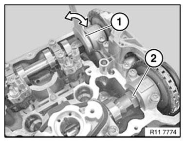
Fig. 239: Rotating Exhaust Camshaft At Dihedron With Fork Wrench Into
Suitable Position
Release bolts of camshaft bearings in sequence (10 to 1) in 1/2 turns.
Set down all bearing caps in a tidy and orderly fashion on special tool 11 4 480.
Remove roller tappet from bearing cap (2 and 3) of high pressure pump and set down on special tool 11 4 480.
Remove left exhaust camshaft and set down on special tool 11 4 480.

Fig. 240: Identifying Camshaft Bearings Bolts Releasing Sequence
IMPORTANT: Used rocker arms (1) may only be reused in the same position.
NOTE: Rocker arms (1) are freely accessible after exhaust camshaft has been removed.
Do "not" remove rocker arms (1) on exhaust side.

Fig. 241: Identifying Rocker Arm
IMPORTANT: Plain compression rings (1) can easily break.
If necessary, replace plain compression rings (1).
Press compression ring (1) on one side into groove, pull up on other side and remove catch.
Carefully pull compression ring (1) apart and remove towards front.
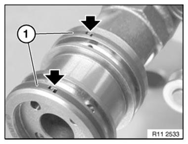
Fig. 242: Locating Compression Ring End
Ends of compression rings (1) point upwards.
Make sure compression rings (1) are engaged at ends.
NOTE: Exhaust camshaft of cylinder bank 5 to 8 is marked with "A 5-8".
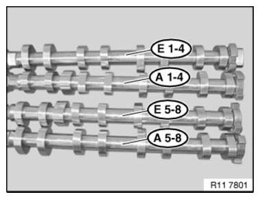
Fig. 243: Identifying Camshaft Of Cylinder Bank Mark
IMPORTANT: Rocker arms (1) slip slightly when exhaust camshaft is fitted.
Make sure rocker arms (1) are secured as illustrated on hydraulic valve clearance compensating elements and on valves.
Align all rocker arms (1) straight.

Fig. 244: Identifying Rocker Arm
Coat all bearing positions with engine oil.
Install exhaust camshaft (1).
Insert exhaust camshaft (1) so that cams point to side at cylinder 5 as shown in picture.
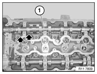
Fig. 245: Identifying Exhaust Camshaft
IMPORTANT: Do not mix up the bearing caps of cylinders 1 to 4 and 5 to 8.
All bearing caps are coded and can only be installed in one position.
All bearing caps are marked:
L= Cylinders 1 - 4.
R= Cylinders 5 - 8.
E= Intake side
A= Exhaust side
1= designation from 1 to 5
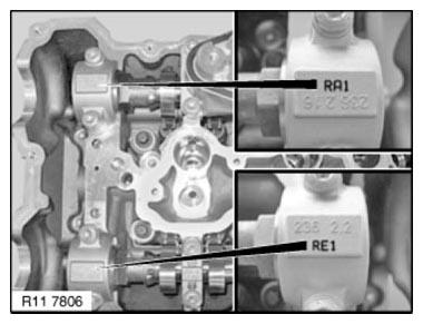
Fig. 246: Identifying Bearing Caps Mark
Insert all bolts.
Tighten down bolts in sequence (1 to 10) in 1/2 turns.
Tightening torque: 11 31 6AZ.
Tightening torque: 11 31 7AZ.
Insert tappets for high-pressure pump.
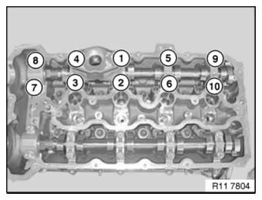
Fig. 247: Identifying Camshaft Bearings Bolts Tightening Sequence
Install INLET ADJUSTMENT UNITS.
Adjust VALVE TIMING.
Assemble engine.
READ NEXT:
 Removing And Installing/Replacing Left Inlet Camshaft (N63)
Necessary preliminary work
(cylinder bank 5 to 8)
IMPORTANT: The intake camshaft must first be rotated in such a way that
the camshaft is
free from tension when the bearing caps are released (risk of
Removing And Installing/Replacing Right Inlet Camshaft (N63)
Necessary preliminary work
(cylinder bank 1 to 4)
IMPORTANT: The intake camshaft must first be rotated in such a way that
the camshaft is
free from tension when the bearing caps are released (risk of
Removing Hydraulic Chain Tensioner For Timing Chains On Left Side
(N63)
Notes
WARNING: Chain tensioner is pre-tensioned.
Release lock pin only in installed state.
Danger of injury!
IMPORTANT: Risk of damage!
The engine must not be cranked when the chain tensioner is rem
SEE MORE:
Vehicle care- Caring for special components
Caring for special components
Light-alloy wheels
When cleaning the vehicle, use only neutral
wheel cleaners having a pH value from 5 to 9. Do
not use abrasive cleaning agents or steam jets
above 140 ℉/60 ℃. Follow the manufacturer's
instructions.
Aggressive, acidic or alkaline cleaning agents c
System Components
Control Units, Control Elements and Spindle Drives
Luggage Compartment Lid Lift
The luggage compartment lid lift is fitted on the right-hand side in the
luggage compartment floor. The HKL
controls and monitors the operation of the automatic luggage compartment lid
actuating system.
The control lo
