BMW 7 Series: Removing And Installing/Renewing Right Exhaust Camshaft (N63)
Notes
Cylinders 1-4:
IMPORTANT: Risk of damage! The exhaust camshaft must first be rotated in such a way that the camshaft is free from tension when the bearing caps are released.
Necessary preliminary work
- Remove right HIGH-PRESSURE PUMP
- Remove right CYLINDER HEAD COVER
- Remove right EXHAUST CAMSHAFT ADJUSTER
IMPORTANT: No cam on the exhaust camshaft is permitted to press directly onto a roller cam follower.
With cylinder no. 1 at 150º before TDC firing position there is no piston in the TDC position.
Rotate exhaust camshaft (2) at dihedron with a fork wrench into a suitable position.
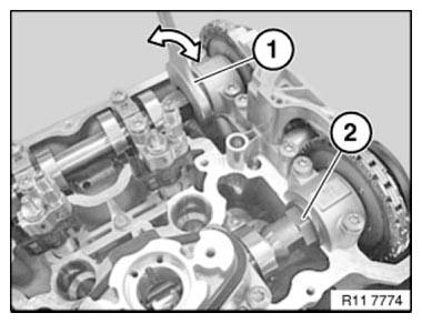
Fig. 228: Rotating Exhaust Camshaft At Dihedron With Fork Wrench Into
Suitable Position
NOTE: The intake camshaft of cylinder bank 5-8 is marked "E 5-8".
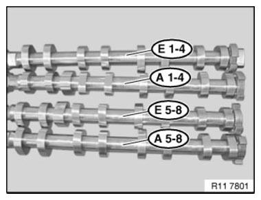
Fig. 229: Identifying Camshaft Of Cylinder Bank Mark
Release bolts of camshaft bearings in sequence (10 to 1) in 1/2 turns.
Set all bearing caps down in special tool 11 4 480 in a neat and orderly fashion.
Remove roller tappet from bearing caps (2 and 3) of high pressure pump and lay down in special tool 11 4 480.
Remove left exhaust camshaft and lay down in special tool 11 4 480.

Fig. 230: Identifying Camshaft Bearings Bolts Releasing Sequence
IMPORTANT: Rocker arms (1) of can slip slightly when inlet camshaft is fitted.
Make sure rocker arms (1) are secured as illustrated on hydraulic valve clearance compensating elements and on valves.
Align all rocker arms (1) straight.
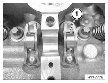
Fig. 231: Identifying Rocker Arm
IMPORTANT: Plain compression rings (1) can easily break.
If necessary, replace plain compression rings (1).
Press compression ring (1) on one side into groove, pull up on other side and remove latch mechanism.
Carefully pull compression ring (1) apart and remove towards front.
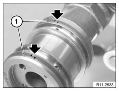
Fig. 232: Locating Compression Ring End
Ends of compression rings (1) point upwards.
Make sure compression rings (1) are engaged at ends.
Coat all bearing positions with engine oil.
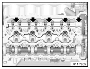
Fig. 233: Locating Bearing Positions
Install exhaust camshaft (1).
Turn exhaust camshaft (1) until cams point to side at cylinder no. 1 as shown in graphic.
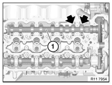
Fig. 234: Identifying Exhaust Camshaft
IMPORTANT: Bearing caps of cylinders 1-4 and cylinders 5-8 must not be interchanged.
All bearing caps are coded and can only be installed in one position.
All bearing caps are marked with letters and numbers:
L= Cylinder bank 1-4.
R= Cylinder bank 5-8.
E= Intake side
A= Exhaust side
1= Marking, bearing point, from 1 to 5
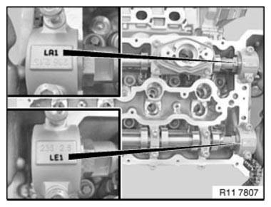
Fig. 235: Identifying Bearing Caps Marks
Insert all bolts.
Tighten down bolts in sequence (1 to 10) in 1/2 turns.
Tightening torque 11 31 6AZ.
Tightening torque 11 31 7AZ.
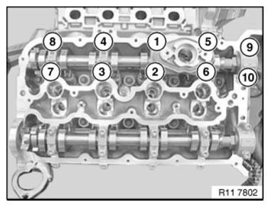
Fig. 236: Identifying Camshaft Bearings Bolts Tightening Sequence
Install right INLET AND EXHAUST CAMSHAFT ADJUSTERS.
Adjust VALVE TIMING.
Assemble engine.
READ NEXT:
 Removing And Installing/Renewing Rocker Arms On Right Side (N63)
Necessary preliminary work
(cylinder bank 1 to 4)
Remove INLET AND EXHAUST ADJUSTMENT UNIT on right side.
Remove right INLET CAMSHAFT.
Remove right EXHAUST CAMSHAFT.
IMPORTANT: Used rocker arms (
Removing And Installing/Replacing Left Inlet Camshaft (N63)
Necessary preliminary work
(cylinder bank 5 to 8)
IMPORTANT: The intake camshaft must first be rotated in such a way that
the camshaft is
free from tension when the bearing caps are released (risk of
Removing And Installing/Replacing Right Inlet Camshaft (N63)
Necessary preliminary work
(cylinder bank 1 to 4)
IMPORTANT: The intake camshaft must first be rotated in such a way that
the camshaft is
free from tension when the bearing caps are released (risk of
SEE MORE:
Danger Of Poisoning If Oil Is Ingested/Absorbed Through The Skin
Danger of poisoning!
Ingesting oil or absorbing through the skin may cause poisoning!
Possible symptoms are:
Headaches
Dizziness
Stomach aches
Vomiting
Diarrhoea
Cramps/fits
Unconsciousness
Protective measures/rules of conduct
Pour oil only into appropriately marked containers
Do not pou
AFGS (Active Pedestrian Protection) Procedure After Accident
The AFGS system consists of the following components:
Satellites (control unit + sensor)
Sensors, inside, bumper trim, left/middle/right
ACSM control unit (Crash Safety Module)
Cables and connectors
Engine compartment lid hinges
Actuator
Engine compartment lid hinge
Engine compa
