BMW 7 Series: Handheld Computer
REMOVING AND INSTALLING (REPLACING) HANDSFREE CHARGING ELECTRONICS (HIGH)
Operation is described in:
REMOVING AND INSTALLING (REPLACING) HANDSFREE CHARGING ELECTRONICS (OPTIONAL EXTRA SA644)
Replacement
- Carry out VEHICLE PROGRAMMING/ENCODING
REMOVING AND INSTALLING (REPLACING) HANDSFREE CHARGING ELECTRONICS (OPTIONAL EXTRA SA644)
IMPORTANT: Read and comply with notes on protection against electrostatic damage (ESD PROTECTION).
NOTE: Comply with notes and instructions on HANDLING OPTICAL FIBRES.
Necessary preliminary tasks
- Clamp off BATTERY NEGATIVE LEAD
- Remove LEFT LUGGAGE COMPARTMENT WHEEL ARCH TRIM
- Partially remove wheel arch panel left at F10
Unlock plug connections (1) and disconnect.
Unscrew nuts (2).
Remove hands-free charging electronics (3).
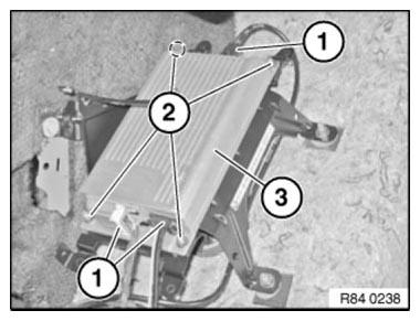
Fig. 11: Identifying Hands-Free Charging Electronics With Plug Connections
And Nuts
Replacement
- Carry out VEHICLE PROGRAMMING/ENCODING
- If necessary, log mobile phone on to vehicle
REMOVING AND INSTALLING/REPLACING HANDS-FREE CHARGING ELECTRONICS (HIGH) (USB/AUDIO INTERFACE) (OPTION SA633/SA639)
IMPORTANT: Read and comply with notes on protection against electrostatic damage (ESD PROTECTION).
NOTE: Comply with notes and instructions on HANDLING OPTICAL FIBRES.
Necessary preliminary work
- Clamp off BATTERY NEGATIVE LEAD
- Disconnect both negative battery cables for F03
- Remove LEFT LUGGAGE COMPARTMENT WHEEL ARCH PANEL
- If necessary, remove AMPLIFIER (without F03)
Unlock plug connections (1) and disconnect.
Unfasten screws (2).
Remove hands-free charging electronics (3).
Installation note: Make sure plug connections are correctly engaged.
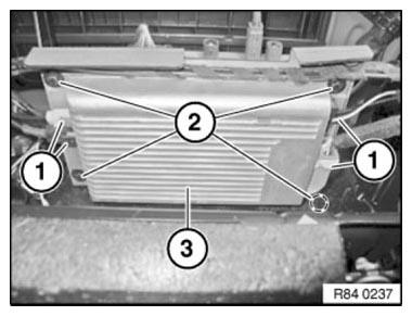
Fig. 12: Identifying Hands-Free Charging Electronics With Plug Connections
And Nuts
Replacement
- Carry out VEHICLE PROGRAMMING/ENCODING
READ NEXT:
 Hands-Free System, Microphone, Speaker
REMOVING AND INSTALLING/REPLACING HANDS-FREE MICROPHONE, DRIVER'S
SIDE
Lever out microphone cover (1) at front in direction of arrow.
Disconnect plug connection underneath and remove microphone cover
Antenna
REMOVING AND INSTALLING/REPLACING BLUETOOTH AERIAL (UP TO 03/2010)
Necessary preliminary tasks
Remove BOTH TRIM PANELS FOR ROOF PILLAR
Remove BOTH REAR GRAB HANDLES
Remove INTERIOR ROOF LIGHT
Rem
SEE MORE:
Controller
MANUAL EMERGENCY RELEASE OF TRANSMISSION LOCK
Manual emergency release of transmission lock from inside vehicle is not
possible with GA6HP/GA8HP gearboxes from
03/2010
From production date 04/2010 on, the transmission lock release cable is
not fitted on:
F01/F02/F03 GA6HP from production date
Removing And Installing/Replacing Sensor For Fuel Gauge
Recycling
Fuel escapes when fuel lines are detached. Have a suitable collecting
container ready.
Catch and dispose of escaping fuel.
Observe country-specific waste-disposal regulations.
IMPORTANT: Ensure adequate ventilation in the place of work!
Avoid skin contact (wear gloves)!
Ensure absolute
