BMW 7 Series: Antenna
REMOVING AND INSTALLING/REPLACING BLUETOOTH AERIAL (UP TO 03/2010)
Necessary preliminary tasks
- Remove BOTH TRIM PANELS FOR ROOF PILLAR
- Remove BOTH REAR GRAB HANDLES
- Remove INTERIOR ROOF LIGHT
- Remove UPPER B-PILLAR TRIM
- Remove BOTH FRONT GRAB HANDLES
Remove auxiliary brake light trim (1) in direction of arrow from headlining (2).
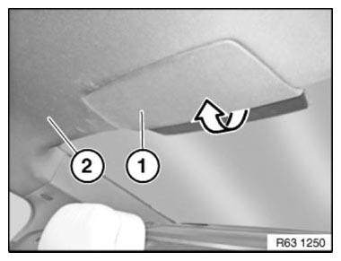
Fig. 16: Removing Auxiliary Brake Light Trim
Unclip headlining.
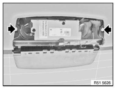
Fig. 17: Locating Headlining Mounting Bolt
Release screw (1).
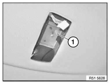
Fig. 18: Identifying Screw
Partially lower headlining (1).
Installation note: Make sure edge protection (2) is correctly seated.
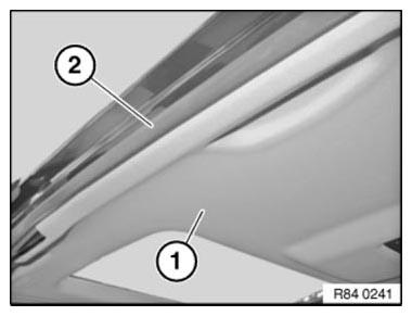
Fig. 19: Identifying Lower Headlining And Edge Protection
Unfasten plug connection (1) and disconnect.
Unclip Bluetooth aerial (2) and remove.
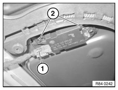
Fig. 20: Identifying Bluetooth Aerial And Plug Connection
REMOVING AND REFITTING/REPLACING BLUETOOTH AERIAL (03/2010 ON)
Necessary preliminary tasks
Remove REAR LEFT DOOR SILL COVER STRIP
Lay floor trim (1) to one side.
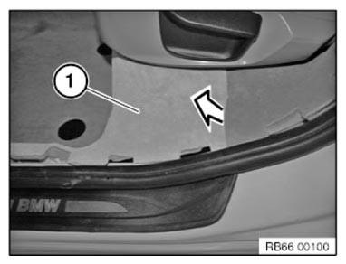
Fig. 21: Laying Floor Trim
Unclip Bluetooth aerial (1) in direction of arrow.
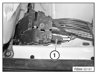
Fig. 22: Removing Bluetooth Aerial
NOTE: Bluetooth aerial lead is connected to Telematic Control Unit/Combox.
F01, F02, F03, F04, F10, F11, F18
Telematic Control Unit/Combox is located underneath LUGGAGE COMPARTMENT LEFT WHEEL ARCH PANEL
F07
Telematic Control Unit/Combox is located underneath spare wheel well front trim panel Expose Bluetooth aerial lead to Telematic Control Unit/Combox and unplug connector.
REMOVING AND INSTALLING/REPLACING EMPTY HOUSING FOR ROOF-MOUNTED AERIAL
Notes
WARNING: Risk of injury! Special tool has sharp edges! Adapt working height to vehicle height with non-tilting and non-slip platform.
Handle special tool correctly and make sure it is positioned without tilting or slipping on the vehicle.
Risk of damage! In order to prevent dents in the roof, do not exert any pressure on the roof.
IMPORTANT: Note to customer:
In order to guarantee a permanent connection and adhesive curing:
After bonding the empty housing for the roof-mounted aerial, wait 24 hours before driving the vehicle through a car wash.
NOTE: Clean roof.
Mask roof (2) around empty housing for roof-mounted aerial (3) with yellow plastic adhesive tape (1). To do so, slide plastic adhesive tape under empty housing (3) slightly.
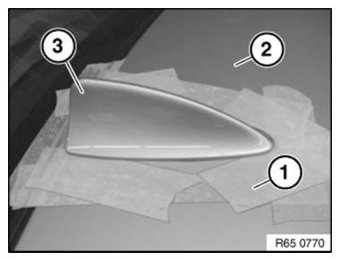
Fig. 23: Identifying Roof With Adhesive Tape And Housing
IMPORTANT: Risk of damage! Make sure your arms do not cross over (1) when holding special tool 65 2 010.
Pull handle must always be ahead of the guiding hand (2).
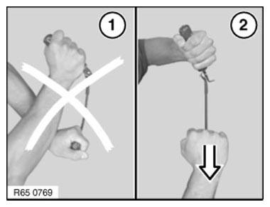
Fig. 24: Identifying Proper Position Of Holding Special Tool
IMPORTANT: Risk of damage!
To avoid damaging the paintwork on the roof and empty housing (3), do not fit special tool 65 2 010 skew.
Cut through adhesive bead all round with special tool 65 2 010.
Pull on handle (1) and align blade on handle (2).
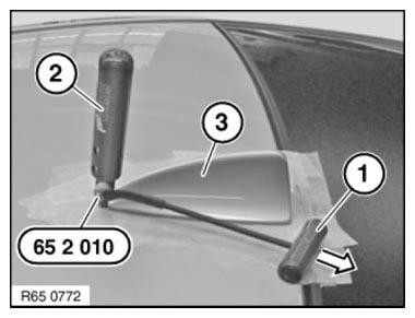
Fig. 25: Cutting Adhesive Bead Using Special Tool 65 2 010
NOTE: Use sharp blades only. Replace blade if necessary.
- Refer to 65 2 010.
Remove empty housing (3).
Installation
- Empty housing for roof-mounted aerial is secured with window glass adhesive. All preparatory operations correspond to the WINDOW CEMENTING INSTRUCTIONS.
NOTE: Replace empty housing for roof-mounted aerial if centering pins (1) on empty housing are damaged.
Bonding surface (2) must be clean and free from grease.
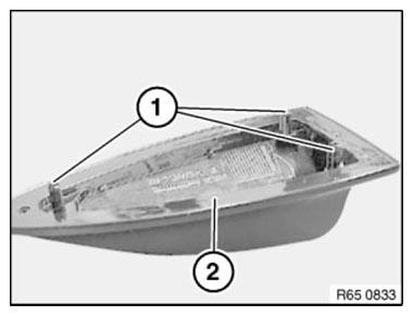
Fig. 26: Identifying Centering Pins And Bonding Surface
Position two spacers (1) on cleaned empty housing.
Dimensions:
- 10 mm
- 14 mm
Position spacer (2) centrally and flush with shoulder of adhesive flange.
IMPORTANT: Use spacers without fail!
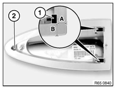
Fig. 27: Identifying Spacer Positions
Apply trace of adhesive bead all round outer contour as follows.
Distance between adhesive bead and edge of aerial cover:
- 6.5 mm +-1 mm
Start and end of bead trace must have an overlap length of max. 10 mm.
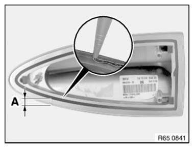
Fig. 28: Identifying Distance Between Adhesive Bead And Edge Of Aerial Cover
IMPORTANT: To prevent the adhesive from escaping, the adhesive bead diameter must not exceed max. 2.5 mm to 4.5 mm.
NOTE: Attach the empty housing coated with adhesive by hand. To spread the adhesive better, move the housing back and forth horizontally slightly when pressing down.
Secure empty housing if necessary with adhesive tape and press down uniformly.
After bonding, leave vehicle to stand for at least 3 hours at room temperature.
READ NEXT:
 Checking Cooling System For Watertightness (N54, N63)
Notes
WARNING: Risk of scalding!
Only perform this repair work after engine has cooled down.
Protective measures/rules of conduct
Wear safety goggles
Wear protective gloves
Observe national/countr
SEE MORE:
External Audio Sources
DVD Changer
The 6-DVD changer is offered as part of the ZPS Premium Sound Package on the
F01/F02 and it is located
above the glove compartment behind the dashboard trim panel. A CD Changer is no
longer offered.
The DVD changer forms part of the MOST network.
A single-slot changer means that the
Removing And Installing/Renewing Pressure Line For VA1 Swivel
Motor
Notes
WARNING: DANGER OF POISONING if oil is ingested/absorbed through the
skin!
RISK OF INJURY if oil comes into contact with eyes and skin!
IMPORTANT: Adhere to the utmost cleanliness. Do not allow any dirt to
enter the hydraulic
system.
Do not draw off hydraulic fluid (risk of contamination).
