BMW 7 Series: Replace Luggage Compartment Floor And Both Side Members (Tail Panel Trim Removed)
Read contents of BODY, GENERAL.
STRIP DOWN VEHICLE.
Place vehicle on straightening bench.
These repair instructions comprise the procedures for REPAIR STAGE 3.
Following new body parts are required:
- Luggage compartment floor, rear
- Side member, left and right
- Extension, side member, left and right
- Luggage compartment floor, left and right
- Fixture, bumper, left and right
Following consumables are required:
MATERIAL CHART
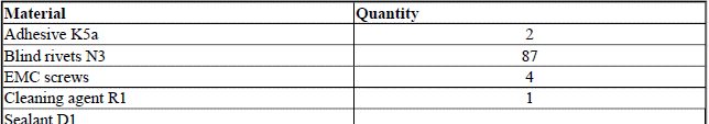
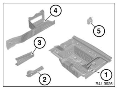
Fig. 153: Identifying, Rear Luggage Compartment Floor And Side Member, Left
And Right
Removing side members and luggage compartment floor
Operation is partially described on the left side. Right side identical.
Open weld joints in area (1).

Fig. 154: Identifying Weld Joints Area
Open weld joints in area (1).

Fig. 155: Identifying Weld Joints Area
Roughly mark severance cut (1) and cut.
Open weld joints in area (2).
Remove luggage compartment floor (3).
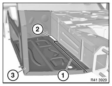
Fig. 156: Identifying Luggage Compartment Floor And Weld Joints Area
View from below.
Open weld joints in area (1).
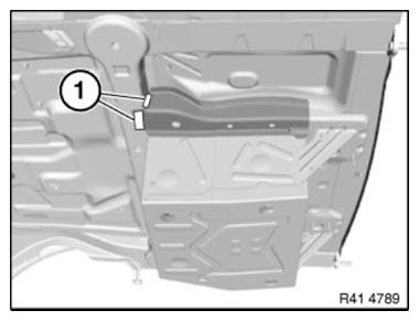
Fig. 157: Identifying Weld Joints Area
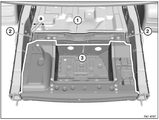
Fig. 158: Identifying Weld Joints Area And Severance Cuts
Mark severance cut (1) approx. 6 mm from edge of component and disconnect.
Mark severance cuts (2) in accordance with measurement and cut.
IMPORTANT: Cut outer metal sheet only.
Measurement a = 25 mm
Open weld joints in area (3).
Remove the luggage compartment floor.
Installation note: Changed joining sequence: Place new component in the areas (1) and (2) from above and install so that it overlaps them.
Mark severance cut (1) flush with side member and cut.
After cutting side member extension (2), open weld joints in area (3).
Installation note: Additionally weld new parts in area (4).
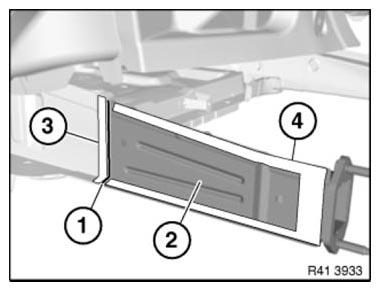
Fig. 159: Identifying Side Member Extension And Weld Joints Area
Mark severance cut (1) flush with side member and cut.
Remove side member extension (2).
Open weld joints in area (3).
Installation note: Additionally weld new parts in area (4) all round.
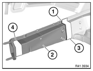
Fig. 160: Identifying Side Member Extension And Weld Joints Area
New part preparation
Operation is partially described on the left side. Right side identical.
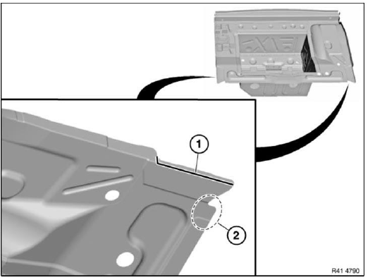
Fig. 161: Identifying Severance Cut And Stampings Fitting Area
Mark severance cut (1) in radius and cut.
Fit stampings in area (2) on the vehicle.
Open weld joints in area (1).
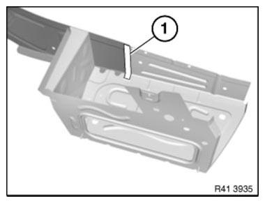
Fig. 162: Identifying Welded Connections Area
Open weld joints in area (1).
Remove metal section (2).
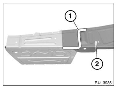
Fig. 163: Identifying Metal Section And Weld Joints Area
NOTE: To adjust new parts to fit, bend side member end panel (1) outwards slightly.
Adjust new parts, side members to fit with alignment bracket or universal mount.
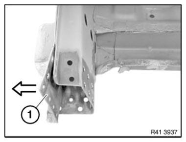
Fig. 164: Bending Side Member End Panel
Set down luggage compartment well (1) from above and adjust in combination with cross member (2) and tail panel to fit and secure.
In areas (1) to (4), set 4.2 mm dia. holes for blind rivets.
BLIND RIVETS HOLES AREA CHART
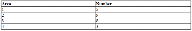
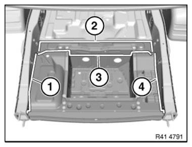
Fig. 165: Identifying Luggage Compartment Well And Cross Member Blind Rivets
Holes Area
Installation note: After adhesive has hardened install 2 EMC SCREWS each in areas (1) and (4).
Adjust side member to fit and secure.
In areas (1) to (4), set 4.2 mm dia. holes for blind rivets.
BLIND RIVETS HOLES AREA CHART
.png)
.png)
Fig. 166: Identifying Side Member Blind Rivets Holes Area
Installation note: New parts are later welded in the area (5).
IMPORTANT: Risk of damage to adjoining adhesive areas! Avoid excessive application of heat.
Adjust boot floor laterally (1) to fit and secure.
Set 5 4.2 mm dia. bore holes in area (2).
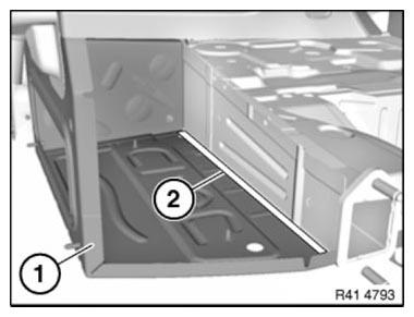
Fig. 167: Identifying Boot Floor Laterally And Bore Holes Area
Set 3 4.2 mm dia. bore holes in area (1).
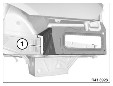
Fig. 168: Identifying Bore Holes Area
Set 11 4.2 mm dia. bore holes in area (1).
Remove new parts and deburr bore holes.
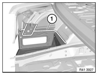
Fig. 169: Identifying Bore Holes Area
IMPORTANT: Do not grind new parts and body in area of bonding surfaces.
Installation of side member
Adjust new parts to fit with straightening attachment or universal mount and weld.
- Extension, side member
- Extension, end plate side member
- Mounting, bumper
Installation of luggage compartment floor
Clean all bonding surfaces with cleaning agent R1.
Apply adhesive to bonding surfaces.
Install new parts and rivet with blind rivets.
READ NEXT:
 Replacing Luggage Compartment Floor, Left Section (Tail Panel Or
Side Wall Removed)
Replacing Luggage Compartment Floor, Left Section (Tail Panel Or
Side Wall Removed)
Read contents of BODY, GENERAL.
STRIP DOWN VEHICLE
NOTE: Observe new procedure for bonding and riveting (REPAIR STAGE 2).
Following new body parts are required:
Luggage compartment floor, left Follo
Replacing Rear Cross Member On Luggage Compartment Floor (Tail
Panel Removed)
Read contents of BODY, GENERAL.
STRIP DOWN VEHICLE
Observe new procedure for bonding and riveting (REPAIR STAGE 2).
Following new body parts are required:
End of luggage compartment floor Following
SEE MORE:
Socket for OBD Onboard
Diagnosis
General information
Devices connected to the OBD socket trigger
the alarm system when the vehicle is locked. Remove
any devices connected at the OBD socket
before locking the vehicle.
Safety information
NOTICE
The socket for Onboard Diagnosis is an intricate
component intended to be used in conjunct
Functions
DSC Functions
Overview
The Dynamic Stability Control on the F01/F02 (DSC F0x) essentially
incorporates the same functions as on the
E70/E71 (DSC E7x).
As the DSC F0x is based on the same highly advanced technology as the DSC E7x,
all DSC functions on the
F01/F02 achieve outstanding performance in
