BMW 7 Series: Replacing Rear Cross Member On Luggage Compartment Floor (Tail Panel Removed)
Read contents of BODY, GENERAL.
STRIP DOWN VEHICLE
Observe new procedure for bonding and riveting (REPAIR STAGE 2).
Following new body parts are required:
- End of luggage compartment floor Following CONSUMABLES are required:
MATERIAL CHART

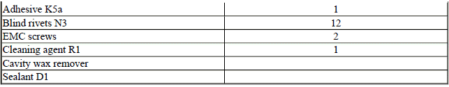
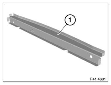
Fig. 181: Identifying End Of Luggage Compartment Floor
Removing cross member
Open welded connections in area (1) and remove cross member (2).
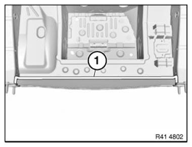
Fig. 182: Identifying Welded Connections Area
New part preparation
Adjust cross-member in combination with tail panel to fit and secure.
Drill 12 dia. 4.2 mm holes for blind rivets in area (1).
Remove new part again and deburr bore holes.

Fig. 183: Identifying Blind Rivets Holes Area
Installing cross member
IMPORTANT: Do not grind new parts and body in area of bonding surfaces.
Clean all bonding surfaces on new part and on vehicle with cleaning agent R1.
Apply adhesive to bonding surfaces.
Install cross member and secure with blind rivets After adhesive has hardened: In the connection area of cross member to side member, fit 2 EMC SCREWS.
STRIPPING OPERATIONS - REPLACING LEFT LUGGAGE COMPARTMENT FLOOR (TAIL PANEL OR SIDE PANEL REMOVED)
NOTE: Owing to the different engine variants and equipment specifications, not all the components are taken into consideration.
The following list basically represents the removal sequence.
- Disconnect battery negative lead (FR number: 61 20 600)
- Remove rear left wheel well cover (FR number: 51 71 041)
- Remove exhaust system (job number: gasoline engine 18 00 020, diesel engine 18 00 018)
- Remove heat shield
- Remove left luggage compartment floor trim panel (job number: 51 47 101)
- Remove left luggage compartment wheel arch panel (job number: 51 47 151)
Release holder (1) for wiring harness and lay to one side.
Release holder for control units (2).
Disconnect plug connections and remove control units (2).
Remove tank venting valve (3).

Fig. 184: Identifying Holder, Control Units And Tank Venting Valve
Release holder for control units (1).
Disconnect plug connections and remove control units (2).
Release cable channel (2) and wiring harness (3) and place to one side.
Release latch mechanisms and remove ventilation (4).
Remove soundproofing (5).

Fig. 185: Identifying Cable Channel, Wiring Harness And Control Units
Stripping Operations - Replacing Luggage Compartment Floor And Both Side Members (Tail Panel Removed)
NOTE: Owing to the different engine variants and equipment specifications, not all the components are taken into consideration.
The following list basically represents the removal sequence.
- Remove left and right rear wheel arch covers (job number: 51 71 041)
- Remove exhaust system (job number: gasoline engine 18 00 020, diesel engine 18 00 018)
- Remove heat shield
Release holder (1) for wiring harness and lay to one side.
Release holder for control units (2).
Disconnect plug connections and remove control units (2).
Remove tank venting valve (3).
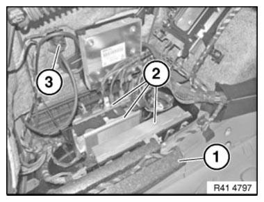
Fig. 186: Identifying Holder, Control Units And Tank Venting Valve
Release holder for control units (1).
Disconnect plug connections and remove control units (1).
Release cable channel (2) and wiring harness (3) and place to one side.
Release latch mechanisms and remove ventilation (4).
Remove sound insulation (5).
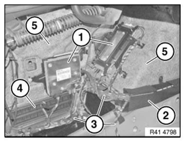
Fig. 187: Identifying Cable Channel, Wiring Harness And Control Units
Release cable channel cover (1) and place to one side.
Remove storage compartment (2).
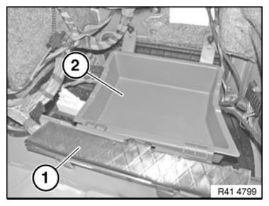
Fig. 188: Identifying Cable Channel Cover And Storage Compartment
Remove power distribution box in passenger compartment (1). Disconnect plug connections and CONTROL UNITS (2) with holder.
Release wiring harness (3) and place to one side.
Release latch mechanisms and remove ventilation (4).
Remove sound insulation (5).
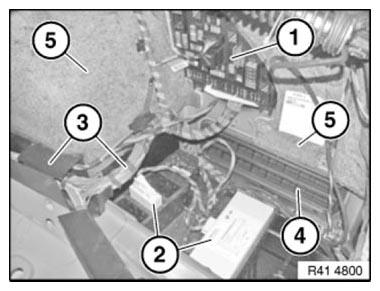
Fig. 189: Identifying Passenger Compartment, Wiring Harness And Ventilation
Remove BATTERY.
Remove NEGATIVE TERMINAL BATTERY CABLE (1).
Release nut (2) and remove ground connection.
Tightening torque 41 34 2AZ.
Disconnect plug connections and remove control units (3).
Release wiring harness (4) and place to one side.
Release positive battery cables (5) and lay to one side.
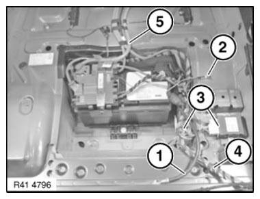
Fig. 190: Identifying Control Units, Wiring Harness And Positive Battery
Cables
STRIPPING OPERATIONS - REPLACING LUGGAGE COMPARTMENT FLOOR, MIDDLE (TAIL PANEL REMOVED)
NOTE: Owing to the different engine variants and equipment specifications, not all the components are taken into consideration.
The following list basically represents the removal sequence.
- Remove exhaust system (job number: 18 00 020)
- Remove heat shield
- Remove spare wheel well trim panel at front and rear.
Remove BATTERY.
Remove BATTERY NEGATIVE LEAD (1).
Release nut (2) and remove earth connection.
Tightening torque 41 34 2AZ.
Disconnect plug connections and remove control units (3).
Release wiring harness (4) and place to one side.
Release positive battery leads (5) and lay to one side.

Fig. 191: Identifying Control Units, Wiring Harness And Positive Battery
Cables
STRIPPING OPERATIONS - REPLACING REAR CROSS-MEMBER ON LUGGAGE COMPARTMENT FLOOR (TAIL PANEL REMOVED)
NOTE: Owing to the different engine variants and equipment specifications, not all the components are taken into consideration.
The following list basically represents the removal sequence.
- Remove negative battery cable (job number: 61 12 013)
- Remove exhaust system (job number: 18 00 020)
- Remove heat shield
READ NEXT:
 Carrying Over Hole Pattern
When replacing a body component, it is necessary to carry over the hole
pattern from the existing body to the
new component.
The following pictures are a schematic representation of carrying over th
Replacing Engine Support With Wheel Arch, Left
Procedure OBSERVE repair stage 3!
Read contents of BODY, GENERAL.
Steel-aluminium composite construction is used on the vehicle. Observe specific
procedure Spot-weld bonding is used on this vehicle.
SEE MORE:
Tire pressure monitor- Actions in the event of a flat tire
Normal tires
Identify the damaged tire.
Check the tire inflation pressure in all four
tires, for instance using the tire pressure gage
of a flat tire kit.
For tires with special approval: when the tire
inflation pressure in all four tires is correct, the
Tire Pressure Monitor may not have b
Replacing Low-Pressure Fuel Sensor (N63)
WARNING: Disconnect BATTERY NEGATIVE TERMINAL (risk of fire due to
short-circuiting
on removal).
Electric fuel pump starts up automatically when door is opened!
Carry out installation work on fuel system only with coolant temperature
below 40ºC.
Wear protective goggles.
IMPORTANT: Adhere to condi
