BMW 7 Series: Carrying Over Hole Pattern
When replacing a body component, it is necessary to carry over the hole pattern from the existing body to the new component.
The following pictures are a schematic representation of carrying over the hole pattern on the example of the front wheel arch.
Necessary preliminary tasks
Adjust new part to fit with straightening attachment.
Insert paper stencil (1) between new component (2) and engine carrier and secure with adhesive tape (3).
Carry over contour (4) of new component to stencil.
Remove new component.
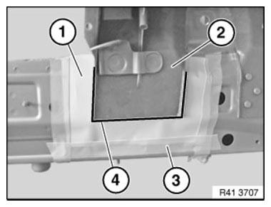
Fig. 192: Securing Paper Stencil Using Adhesive Tape
- contour of new component.
Carry over positions of holes (2) to stencil by pressing down with thumbs.
Remove stencil.
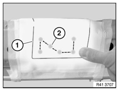
Fig. 193: Carrying Over Positions Of Holes To Stencil
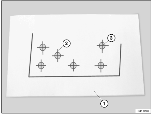
Fig. 194: Identifying Holes With Crosses And Stencil
Lay stencil (1) on a flat surface.
Mark center points of holes with crosses (2).
Then pierce paper through center points (3) of holes with a pointed object.
Align stencil (1) according to contours (2) to inside of new component and secure with adhesive tape (3).
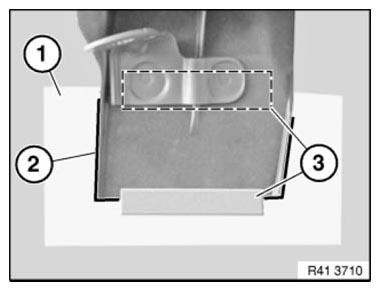
Fig. 195: Securing Stencil To Component Using Adhesive Tape
Turn over new component.
IMPORTANT: Crosses must not be visible in this view!
Set punch marks at pierced center points (1).
Grip directly under punch marks for marking with punch.
Remove stencil (2).
Drill holes to approx. 3 - 4 mm dia. at punch marks (1).
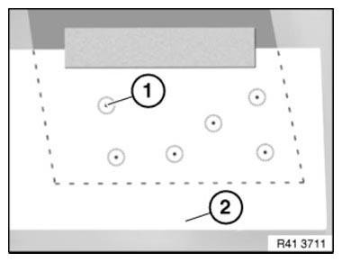
Fig. 196: Identifying Stencil And Punch Marks
Position new component (1) with straightening attachment on vehicle.
Drill out holes (2) to 6.7 mm dia.
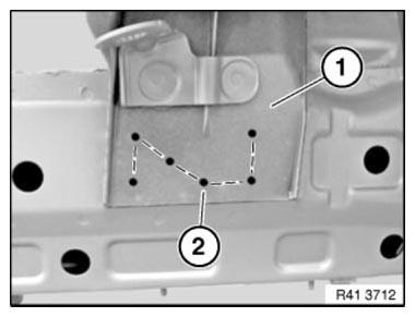
Fig. 197: Identifying Component Position And Drill Holes
READ NEXT:
 Replacing Engine Support With Wheel Arch, Left
Procedure OBSERVE repair stage 3!
Read contents of BODY, GENERAL.
Steel-aluminium composite construction is used on the vehicle. Observe specific
procedure Spot-weld bonding is used on this vehicle.
Replacing Engine Support/Front Left Side Frame Connection (Front
Left Wheel Arch Removed)
Observe procedure for REPAIR STAGE 3.
Read contents of BODY, GENERAL.
To remove engine support side frame connection
Following new body parts are required:
Connection, wheel arch/entrance
Fig. 21
Replacing Front Left Wheel Arch
Note the special vehicle identification number procedure when replacing the
front right wheel arch (order the
new body part with the vehicle identification number, if necessary)!
These instructions a
SEE MORE:
Removing And Installing/Replacing Forward/Back Seat Adjustment Drive Unit
Necessary preliminary tasks
Raise front seat as far up as possible
Remove TRIMS ON UPPER RAILS
Procedure in event of faulty drive for forward/back seat adjustment:
Removing forward/back seat adjustment motor
Unfasten plug connection (1) and disconnect.
Fig. 42: Identifying Forward/Back Seat Ad
Replacing Complete Tail Panel
Read contents of BODY, GENERAL.
STRIP DOWN VEHICLE.
NOTE: Observe new procedure for bonding and riveting (REPAIR STAGE 2).
Operation is partially described on the left side. Right side identical.
Following new body parts are required (refer to Electronic Parts Catalogue -
EPC):
Rear panel
Follo
