BMW 7 Series: Replace The A-Pillar On The Outside Left In The Area Of The Windscreen
Read contents of BODY, GENERAL.
Remove or cover those vehicle components in the repair area which are susceptible to heat or dust.
Use only approved SPOT-WELDING APPARATUS for repairs.
IMPORTANT: Operations on pyrotechnical devices may only be carried out by authorized experts.
Improper, unauthorized operations may result in serious dangers.
Unauthorized persons are strictly prohibited from performing any operations on this system.
WARNING: Read and comply with SAFETY REGULATIONS for handling airbag modules and pyrotechnical belt tensioners.
Incorrect handling can activate airbag and cause injury.
A damaged head airbag must be replaced.
A damaged head airbag exhibits an impaired protective function and in extreme cases loses its protective function altogether.
Necessary preliminary work
Disconnect BATTERY NEGATIVE LEAD
Remove PANEL FOR ROOF PILLAR Following new body parts are required:
- A-pillar, outer
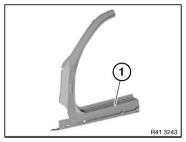
Fig. 307: Identifying A-Pillar, Outer
Unclip wiring harness in area (1).
Release screws (2) for airbag.
IMPORTANT: Risk of damage! Airbag (3) must not be kinked or bent!
Installation note: Tightening torque 72 12 02AZ.
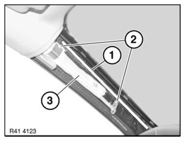
Fig. 308: Identifying Wiring Harness Area, Screws And Airbag
NOTE: Use protective sleeve (1) to protect the airbag.
Check protective sleeve for damage prior to use.
A damaged protective sleeve must not be used!
- Velcro fastener
- Loop
- Order number, protective sleeve: 81 47 2 159 578
Sourcing reference:
BMW Workshop Equipment Catalogue.
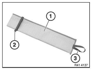
Fig. 309: Identifying Protective Sleeve, Velcro Fastener And Loop
Slide protective sleeve (1) onto airbag under roofliner so that airbag is completely covered.
Fasten protective sleeve with Velcro fastener (2).
Secure protective sleeve with airbag against kinking.
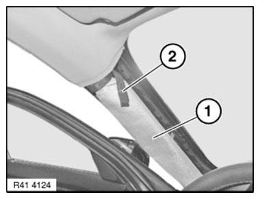
Fig. 310: Identifying Protective Sleeve And Velcro Fastener
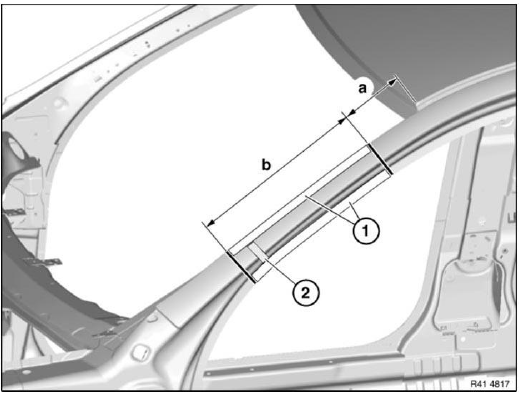
Fig. 311: Identifying Welded Connections Areas
Mark severance cuts in accordance with specified dimensions and cut.
IMPORTANT: Cut outer panel only for following severance cuts.
Measurement a = approx. 150 mm from roof edge.
Measurement b = approx. 380 mm below severance cut a.
Open welded connections in areas (1).
Installation note:
Weld in REINFORCEMENT PLATE at all severance cuts.
Apply window glass adhesive to CAVITY ACOUSTIC BAFFLE (2).
After completing welding work:
Check airbag in area of protective sleeve for damage, replace if necessary.
READ NEXT:
 Replacing Front Left Door Post (Front Side Panel Removed)
Procedure OBSERVE repair stage 3! Read contents of BODY, GENERAL.
Spot-weld bonding is used on this vehicle. Observe specific procedure See
SPOT-WELD BONDING
STEEL PARTS.
Place vehicle on straighte
Front Trim Panel
Replacing Front Left Or Right Side Wall Holder
NOTE: Read CONTENTS OF BODY, GENERAL.
Side wall removed.
Transfer the systematic diagram onto the respective holder version.
NOTE: Observe REPAIR STAGE
SEE MORE:
Active Roll Stabilization (ARS)
General Information
Active Roll Stabilization was first fitted on the 7 Series predecessor, the
E65/E66, and has been used in similar
form since on the E6x and E7x models.
This section only describes the essential details and modifications of the ARS
on the F01/F02.
As Vertical Dynamics Control
Notes In The Event Of Vehicle Inclination
System-related causes (no faults)
Control tolerance when "Ignition off", but vehicle is awake (e. g.
hazard warning switch is lit): +- 7
mm (applies from integration level 10-06-500 or CAF 4.5.4-> Read out SVK;
earlier versions +- 15
mm) relative to nominal ride-level height (attention: a
