BMW 7 Series: Front Trim Panel
Replacing Front Left Or Right Side Wall Holder
NOTE: Read CONTENTS OF BODY, GENERAL.
Side wall removed.
Transfer the systematic diagram onto the respective holder version.
NOTE: Observe REPAIR STAGE 2.
The following new body parts are required (refer to BMW Electronic Parts Catalogue):
- Holder, side wall, front (variant 1)
- Holder, side wall, front (variant 2)
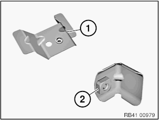
Fig. 321: Identifying Holder Variants
The following CONSUMABLES are required:


Removal of side wall holder (variant 1): Release welded connections in areas (1) and remove holder (2).
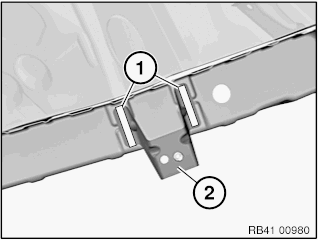
Fig. 322: Removing Holder
Preparation of new part: Adjust new part in conjunction with side panel in front to fit.
In area of bonding surfaces (1), set 2 4.2 mm dia. bore holes (2) for blind rivetsN3.
Remove new part and deburr holes.
IMPORTANT: Do not grind bonding surfaces down or off.
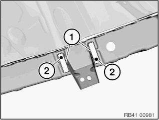
Fig. 323: Identifying Locations For Bore Holes
Installation of side wall holder: Clean all bonding surfaces with cleaning agent R1.
Apply adhesive to bonding surfaces.
Install new part and rivet with blind rivets.
Removal of side wall holder (variant 2): Release welded connection in area (1) and remove holder (2).
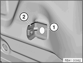
Fig. 324: Removing Holder
Preparation of new part: Fit in new part.
In area of adhesive surface (1), drill a 4.2 mm dia. bore hole (2) for blind rivet N3.
Remove new part and deburr holes.
IMPORTANT: Do not grind bonding surfaces down or off.
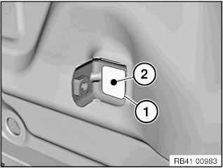
Fig. 325: Identifying Location For Bore Hole
Installation of side wall holder: Clean all bonding surfaces with cleaning agent R1.
Apply adhesive to bonding surface.
Install new part and rivet with blind rivet.
READ NEXT:
 Replacing Complete Tail Panel
Read contents of BODY, GENERAL.
STRIP DOWN VEHICLE.
NOTE: Observe new procedure for bonding and riveting (REPAIR STAGE 2).
Operation is partially described on the left side. Right side identical.
Fol
Replacing Luggage Compartment Floor, Left Section (Tail Panel Or
Side Wall Removed)
Read contents of BODY, GENERAL.
STRIP DOWN VEHICLE
NOTE: Observe new procedure for bonding and riveting (REPAIR STAGE 2).
Following new body parts are required (refer to Electronic Parts Catalogue -
SEE MORE:
Stripping Operations - Replacing Rear Left Side Panel
NOTE: Owing to the different engine variants and equipment specifications,
not all the
components are taken into consideration.
The following list basically represents the removal sequence.
Clamp off battery negative lead (job number: 6120 900)
Remove bumper trim (job number: 5112156)
Remove bu
Replacing Wiring Harness Section For Ignition And Injectors (N63)
IMPORTANT: Read and comply with notes on protection against damage from
electrostatic
damage (ESD protection).
Necessary preliminary work
Read out the fault memory of the DME control unit.
Switch off ignition.
Disconnect BATTERY EARTH LEAD.
Remove left and right INTAKE SILENCER HOUSINGS.
Remo
