BMW 7 Series: Replacing Complete Tail Panel
Read contents of BODY, GENERAL.
STRIP DOWN VEHICLE.
NOTE: Observe new procedure for bonding and riveting (REPAIR STAGE 2).
Operation is partially described on the left side. Right side identical.
Following new body parts are required (refer to Electronic Parts Catalogue - EPC):
- Rear panel
Following consumables are required:
MATERIAL CHART
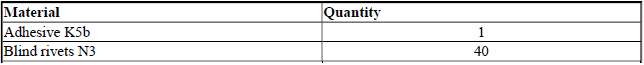
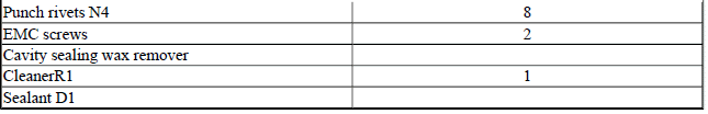
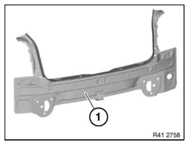
Fig. 326: Identifying Rear Panel
Removing rear trim panel Release screws (1) and remove support (2).
Tightening torque 41 34 1AZ.
Version with automatic tailgate actuation: Shut down automatic read lid actuation.
IMPORTANT: Risk of damage to spindle drive: only move tailgate slowly by hand.
If necessary, remove spindle drive.
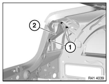
Fig. 327: Identifying Screws And Support
Open welded connections in areas (1).
Open welded connections in areas (2) from inside.
Remove rear trim.
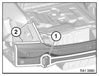
Fig. 328: Identifying Welded Connections Areas
Preparation of new part
Slide in rear panel (1) from below in upward direction and adjust to fit and secure in conjunction with tailgate and rear lights.
NOTE: On vehicles with a sensor for lane change warning , also check the bumper guide for correct seating.
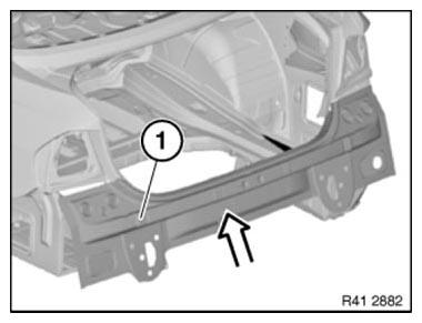
Fig. 329: Sliding Rear Trim Panel
IMPORTANT: Fixing screws must not be used in area (1)
In areas (2 to 5) set 4.2 mm dia. holes for blind rivets: N3
BLIND RIVETS HOLES AREA CHART
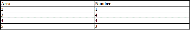
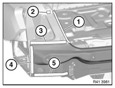
Fig. 330: Identifying Blind Rivet Holes Area
In area (1) set 8 holes for blind rivets N3. In so doing, drill the two outer holes from the inside outwards.
Then connect the outer holes on the outside with a line. Drill the remaining holes on the line from the outside.
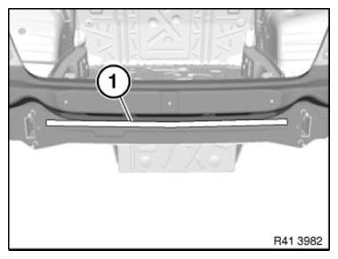
Fig. 331: Identifying Blind Rivet Holes Area
In area (1) set seven 4.2 mm holes for N3 blind rivets.
IMPORTANT: No blind rivets may be used in areas (2)! Dimension A = 10 cm
Remove new part again and deburr holes.
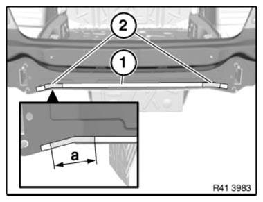
Fig. 332: Identifying Blind Rivet Holes Area
IMPORTANT: Do not grind/sand new part in area of bonding surfaces.
Installing rear trim panel
Clean all bonding surfaces on new part and on vehicle with cleaning agent R1.
Apply adhesive K5b to bonding surfaces.
Make sure adhesive application is closed in area (1)! (watertightness).

Fig. 333: Identifying Rear Panel Adhesive Application Area
Slide in rear trim panel (1) from bottom upwards.
Rivet rear panel.
NOTE: When sliding in rear trim panel, make sure there is sufficient adhesive on bonding surfaces.

Fig. 334: Sliding Rear Trim Panel
In area (1), rivet tail panel with 4 punch rivets N4.
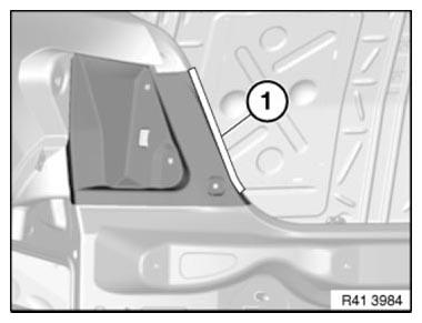
Fig. 335: Identifying Tail Panel Punch Rivets Area
Press rear panel in area (1) and remove emerging adhesive.
Before the adhesive has hardened, install the support for the bumper trim.
IMPORTANT: Prevent emerging adhesive from coming into contact with support.
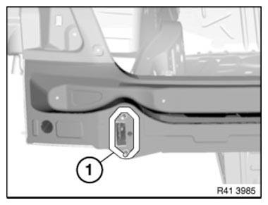
Fig. 336: Identifying Rear Panel Adhesive Application Area
After adhesive has hardened:
In areas (2), use 2 EMC SCREWS.
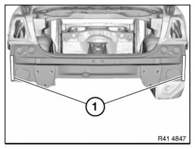
Fig. 337: Identifying Adhesive Areas
READ NEXT:
 Replacing Luggage Compartment Floor, Left Section (Tail Panel Or
Side Wall Removed)
Replacing Luggage Compartment Floor, Left Section (Tail Panel Or
Side Wall Removed)
Read contents of BODY, GENERAL.
STRIP DOWN VEHICLE
NOTE: Observe new procedure for bonding and riveting (REPAIR STAGE 2).
Following new body parts are required (refer to Electronic Parts Catalogue -
Replacing Rear Cross Member On Luggage Compartment Floor (Tail
Panel Removed)
Read contents of BODY, GENERAL.
STRIP DOWN VEHICLE
Observe new procedure for bonding and riveting (REPAIR STAGE 2).
Following new body parts are required:
End of luggage compartment floor
Followi
Stripping Operations - Replacing Rear Left Side Panel
NOTE: Owing to the different engine variants and equipment specifications,
not all the
components are taken into consideration.
The following list basically represents the removal sequence.
Clamp o
SEE MORE:
Glass sunroof- Jam protection system
Concept
The jam protection prevents objects or body
parts from becoming jammed between the roof
and glass sunroof while the glass sunroof is closing.
General information
If a resistance or blockage is detected while the
glass sunroof is closing, the closing operation is
interrupted once the roof rea
Replacing Low-Pressure Fuel Sensor (N63)
WARNING: Disconnect BATTERY NEGATIVE TERMINAL (risk of fire due to
short-circuiting
on removal).
Electric fuel pump starts up automatically when door is opened!
Carry out installation work on fuel system only with coolant temperature
below 40ºC.
Wear protective goggles.
IMPORTANT: Adhere to condi
