BMW 7 Series: Replacing Front Left Door Post (Front Side Panel Removed)
Procedure OBSERVE repair stage 3! Read contents of BODY, GENERAL.
Spot-weld bonding is used on this vehicle. Observe specific procedure See SPOT-WELD BONDING STEEL PARTS.
Place vehicle on straightening bench.
Following new body parts are required:
- A-pillar, outer
- Connection, side frame
- Shaped part, carrier support, wheel arch, front (not shown)
- Shaped part, carrier support, wheel arch (not shown)
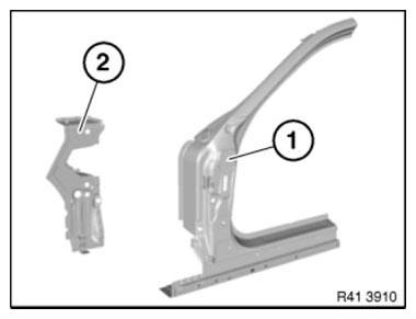
Fig. 312: Identifying Connection, Side Frame And A-Pillar, Outer
Open spot-welded adhesive joint in area (1).
Open welded connections in areas (2).
Roughly cut side frame connection along lines (4).
Remove side frame connection (3).
Installation note:
MAG-weld new part in areas (4).
To do so, apply 10 mm long fillet welds at spacing of 15 mm.
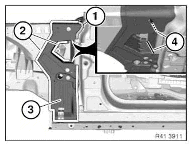
Fig. 313: Identifying Spot-Welded Adhesive Joints Area And Side Frame
Connection
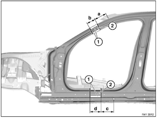
Fig. 314: Identifying Welded Connections Areas And Sheet Sections
Mark severance cuts in accordance with specified dimensions and cut.
IMPORTANT: Cut outer panel only for following severance cuts.
Dimension a = 200 mm from roof edge.
Dimension b = 100 mm below severance cut a.
Dimension c = approx. 165 mm before center of hole diameter 15 mm.
Dimension d = 140 mm before severance cut c.
Open welded connections in areas (1).
Remove sheet sections (2).
Installation note: Cut-out metal sections (2) are required again for sealing.
Weld in REINFORCEMENT PLATES at all severance cuts.
IMPORTANT: For following severance cut, do not damage slide/tilt sunroof water drain hose.
Cut outer panel only.
Mark severance cut (1) in accordance with specified dimension and cut.
Dimension a = approx. 250 mm from roof edge.

Fig. 315: Identifying Roof Edge Cutting Dimension
Mark severance cut (1) in accordance with specified dimension and cut.
IMPORTANT: Cut outer panel only.
Dimension a = approx. 235 mm before center of 15 mm dia. hole.
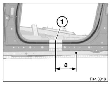
Fig. 316: Identifying Outer Panel Cutting Dimension
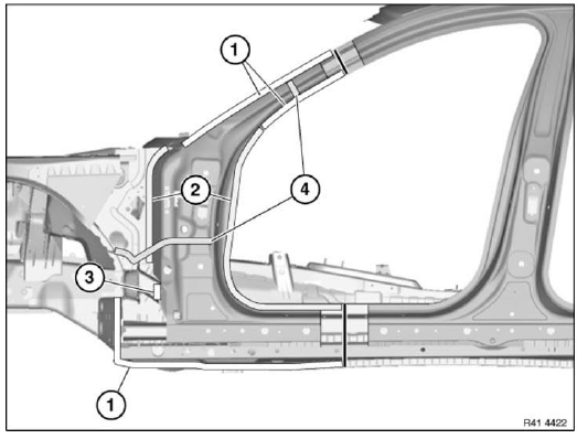
Fig. 317: Identifying Bonded Connection Area, Cavity Sealing And Welded
Connections Areas
Open welded connections in areas (1).
Open spot-welded adhesive joints in areas (2).
Open bonded connection in area (3).
Installation note: Replace bonded connection in area (3) with MAG weld seam.
Apply sealant to cavity sealing (4).
View from below.
Open welded connection (1).
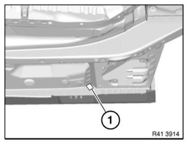
Fig. 318: Identifying Welded Connection
View from inside.
Open spot-welded adhesive joint (1 welding spot in each case) in areas (1).
Open welded connection (2).
Feed out sliding sunroof water drain hose (3) and door post.
Installation note: Prepare body in areas (1) for plug welding.
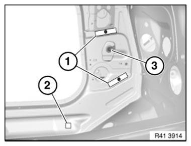
Fig. 319: Identifying Sunroof Water Drain Hose, Spot-Welded Adhesive Joint
Areas And Welded
Connection
Installation note: Apply repair welding spots in area (1) to existing welding spots on new part/vehicle. This is necessary because the adhesive between the spot flanges acts as an insulator.
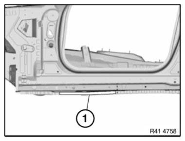
Fig. 320: Identifying Welding Spots Area
Installation note:
Mark new part in accordance with severance cuts above and cut.
Adjust new part to fit with alignment bracket or universal mount.
Make sure water drain hose is correctly fitted.
READ NEXT:
 Front Trim Panel
Replacing Front Left Or Right Side Wall Holder
NOTE: Read CONTENTS OF BODY, GENERAL.
Side wall removed.
Transfer the systematic diagram onto the respective holder version.
NOTE: Observe REPAIR STAGE
Replacing Complete Tail Panel
Read contents of BODY, GENERAL.
STRIP DOWN VEHICLE.
NOTE: Observe new procedure for bonding and riveting (REPAIR STAGE 2).
Operation is partially described on the left side. Right side identical.
Fol
SEE MORE:
Functions
Electric Front Seat Adjustment
The seats can be adjusted from terminal 30B ON. The seat-adjustment switch
simply has to be pressed in the
desired direction. The seats can have up to eight adjustment axes.
The seat adjustment options are listed in the following table:
SEAT ADJUSTMENT OPTIONS CHART
Adjusting Fog Lights
Comply with TEST PRECONDITIONS FOR HEADLIGHT ADJUSTMENT.
Necessary preliminary tasks
Remove TRIM GRILLE IN BUMPER TRIM
IMPORTANT: Do not damage adjusting screw when adjusting fog lamp.
Adjust fog lamp (1) at adjusting screw (2).
Fig. 17: Adjusting Fog Lamp
ADJUSTING HEADLIGHTS
OBSERVE TEST PRECO
