BMW 7 Series: Removing And Installing/Replacing Middle Pedestrian Protection Sensor
WARNING: Observe SAFETY INSTRUCTIONS for handling gas generators.
Incorrect handling can activate pedestrian protection and cause injury.
Necessary preliminary work
- Disconnect BATTERY CABLE
- Remove BASEPLATE FOR NUMBER PLATE
- Remove ORNAMENTAL GRILLE IN BUMPER TRIM.
Release screws (1).
Tightening torque 65 76 1AZ.
Feed out sensor (2).
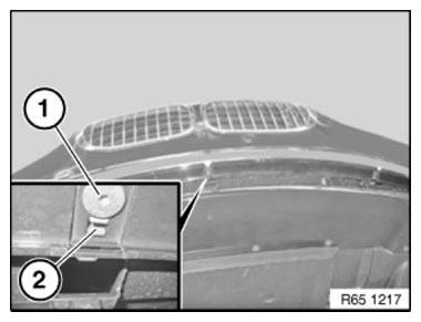
Fig. 120: Identifying Screws And Sensor
Unfasten plug connection (1) and disconnect.
Remove sensor (2).
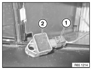
Fig. 121: Identifying Plug Connection And Sensor
REMOVING AND INSTALLING/REPLACING RIGHT B-PILLAR SENSOR
Operation is identical to:
REMOVING AND INSTALLING LEFT B-PILLAR SENSOR
REMOVING AND INSTALLING/REPLACING RIGHT PEDESTRIAN PROTECTION SENSOR
WARNING: Observe SAFETY INSTRUCTIONS for handling gas generators.
Incorrect handling can activate pedestrian protection and cause injury.
Necessary preliminary work
- Disconnect BATTERY CABLE
- Remove ORNAMENTAL GRILLE IN BUMPER TRIM.
Release screws (1).
Tightening torque 65 76 1AZ.
Feed out sensor (2).
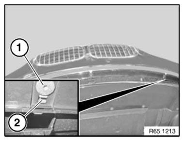
Fig. 122: Identifying Screws And Sensor
Unfasten plug connection (1) and disconnect.
Remove sensor (2).

Fig. 123: Identifying Plug Connection And Sensor
REPLACING SEAT OCCUPANCY MAT FOR FRONT PASSENGER SEAT OCCUPANCY DETECTOR
WARNING: US/CDN front passenger seat (with CIS mat) only: The CIS mat can only be removed from the upholstery together with the seat cover.
If CIS mat, seat cover or seat heating is defective, all parts may only be replaced together.
After fitting seat cover, enable CIS mat with BMW DIAGNOSIS SYSTEM.
Necessary preliminary work
- Remove seat cover for front passenger seat:
- Normal, Electric
- Sports, Electric
- Comfort
NOTE: Graphic is an example.
Pull seat occupancy mat (1) off front passenger seat upholstery (4) and feed out connector housing (3).
Installation note:
- To avoid malfunctions, make sure seat occupancy mat (1) is cleanly laid:
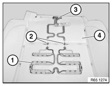
Fig. 124: Identifying Seat Occupancy Mat, Front Passenger Seat Upholstery,
Connector Housing And
Lay Seat Occupancy Mat Bridges
- Lay connector housing (3) in designated recess
- Lay seat occupancy mat bridges (2) cleanly and feed into designated recesses
- Secure seat occupancy mat (1) to bonding surface
- Lay seat occupancy mat (1) straight and without kinks
REPLACING SENSOR MAT (CIS MAT) FOR FRONT PASSENGER SEAT OCCUPANCY DETECTION DETECTOR
F01 and F02 only:
Version with CIS mat from 09/09.
For vehicles built before 08/09, see version with OC3 MAT.
WARNING: Note AIRBAG SAFETY REGULATIONS ! Incorrect handling can lead to airbag deployment and cause injury.
WARNING: Only US and Canadian version of front passenger seat (with CIS mat):
The CIS mat can only be removed from the upholstery together with the seat cover.
If CIS mat, seat cover or seat heating is defective, all parts may only be replaced together.
After fitting the seat cover, the CIS mat must be enabled with the BMW PROGRAMMING SYSTEM.
- Procedure for replacing the CIS mat together with the seat cover is
described in seat cover
replacement:
- Normal, Electric
- Sports, Electric
- Comfort
The work scope with CIS mat is different for the following work steps: Loosen the bolting point (1) of the ground cable on the seat pan.
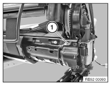
Fig. 125: Identifying Bolting Point
Cut open cable strap (1).
Lift locking tab and pull the connector out of the side of the connector housing.
Installation note: Replace cable tie (1).
Connector is encoded against incorrect assembly.
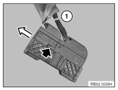
Fig. 126: Identifying Cable Strap And Tie
Installation note:
Enabling seat occupancy detection (CIS mat):
- Connect BMW PROGRAMMING SYSTEM
- Encode airbag control unit
- Delete fault memory if necessary
REPLACING SENSOR MAT (OC3 MAT) FOR FRONT PASSENGER SEAT OCCUPANCY DETECTOR
NOTE: Version with OC3 mat up to version (build date) 08/09.
From version (build date) 09/09, see version with CIS MAT.
WARNING: Note AIRBAG SAFETY REGULATIONS ! Incorrect handling can activate the airbag and cause injury.
WARNING: US/CDN front passenger seat (with OC3 mat) only:
A faulty OC3 mat can only be removed in conjunction with the upholstery from the seat cover.
If OC3 mat or upholstery is defective, both parts may only be replaced together.
After fitting seat cover, enable OC3 mat with BMW diagnosis system.
The operation for removing the OC3 mat in conjunction with the upholstery is described in seat cover replacement:
- Normal, Electric
- Sports, Electric
- Comfort
Enabling seat occupancy detector (OC3 mat):
- Connect BMW PROGRAMMING SYSTEM
- Encode airbag control unit
- Delete fault memory if necessary
On-Board Computer
REMOVE AND INSTALLING/REPLACING OUTSIDE TEMPERATURE SENSOR (N54, N55, N63, N74, N57S)
- Remove FRONT RIGHT WHEEL ARCH COVER (front section)
Unclip outside temperature sensor (1) in direction of arrow from mounting and pull out.
Disconnect plug connection (2) and remove outside temperature sensor (1).
Installation: Clip temperature sensor (1) into place.
Close plug connection (2).
Make sure outside temperature sensor (1) is correctly engaged in mounting.
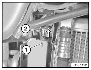
Fig. 127: Identifying Temperature Sensor And Plug Connection
READ NEXT:
 Car Communication Computer (CCC)
REMOVING AND INSTALLING (REPLACING) CAR INFORMATION COMPUTER (CIC)
IMPORTANT: Risk of damage!
A hard disk is installed in the Car Information Computer (CIC).
Carry out mechanical work on the CIC and
Audio, Navigation And Information Systems
KNIFE
Knife MW
Note: (Cutting knife set for roof-mounted aerial (empty housing) ) special
tool for manual operation only. 65 2
011 Drawing knife with plastic sleeve; 65 2 012 Pull handle with plastic
SEE MORE:
Steering Wheel
Removing And Installing/Replacing Sport Steering Wheel
NOTE: Chassis/wheel alignment is not necessary after the steering wheel
has been
removed and installed or replaced.
Necessary preliminary work
Remove AIRBAG UNIT
Move wheels/sport steering wheel into straight-ahead position.
Disconnect plug
Venting And Filling Cooling System With Vacuum Filling Unit
Notes
IMPORTANT: Lifetime coolant filling:
Never reuse used coolant!
When replacing and removing components which rely on the corrosion
protection effect of the coolant, it is essential to change the coolant. The
cooling system must therefore be drained and refilled.
In the case of other removal wo
