BMW 7 Series: Car Communication Computer (CCC)
REMOVING AND INSTALLING (REPLACING) CAR INFORMATION COMPUTER (CIC)
IMPORTANT: Risk of damage!
A hard disk is installed in the Car Information Computer (CIC).
Carry out mechanical work on the CIC and adjacent components with care.
Avoid subjecting the CIC to vibration/shocks.
IMPORTANT: Read and comply with NOTES on protection against electrostatic damage (ESD protection).
NOTE: Comply with notes and instructions on NOTES ON HANDLING OPTICAL FIBRES.
Necessary preliminary work
- F01/02/F07/F10/F11/F12/F13/F1 Disconnect NEGATIVE BATTERY CAB
- F03: Remove both negative batt cables
- Remove RADIO AND A/C CONTROL PANEL
NOTE: Picture for example purposes only!
Unfasten screws (2).
Pull CIC (3) out of guide.
Installation note: Make sure CIC (3) is correctly seated in guide lugs (1).
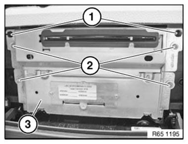
Fig. 128: Identifying Screws, Cic And Guide Lugs
Unlock plug connections (2) and (3) and disconnect.
Remove CIC (1).
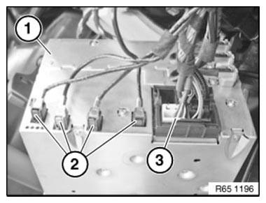
Fig. 129: Identifying Plug Connections And CIC
Only for US models with satellite tuner:
When replacing the CIC unit, additional work is required!
- Refer to REPLACING SATELLITE TUNER, AS OF 09/2009.
Replacement
- Carry out VEHICLE PROGRAMMING AND ENCODING.
REMOVING AND INSTALLING/REPLACING COVER FOR REAR PASSENGER COMPARTMENT MONITOR AT FRONT
IMPORTANT: Read and comply with NOTES on protection against electrostatic damage (ESD protection).
Necessary preliminary work
- Remove COVER FOR REAR PASSENGER COMPARTMENT MONITOR AT REAR
IMPORTANT: Do not damage or scratch display.
Release screws (1).
Tightening torque 65 50 1AZ.
Carefully disconnect plug connection (3).
Remove rear passenger compartment monitor (4) from cover (5).
Installation note: Ensure correct cable routing in guides (2).
Make sure cover (5) is correctly seated on rear passenger compartment monitor (4).
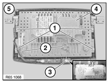
Fig. 130: Identifying Screws, Plug Connection, Guides, Cover And Cable
REMOVING AND INSTALLING/REPLACING LEFT OR RIGHT REAR MONITOR
IMPORTANT: Read and comply with notes on protection against electrostatic damage (ESD PROTECTION).
Installation note:
- Remove REAR PASSENGER COMPARTMENT MONITOR COVER
Release screws (1).
Remove rear passenger compartment monitor (2) from holder (3).
Installation note:
Make sure rear passenger compartment monitor (2) is correctly seated on holder (3).
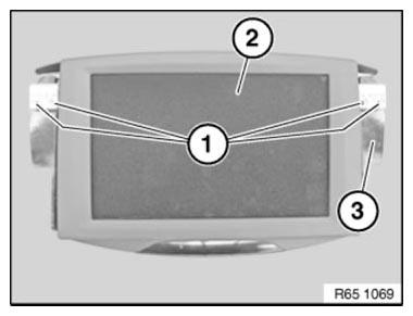
Fig. 131: Identifying Screws, Rear Passenger Compartment Monitor And Holder
Unlock plug connections and disconnect.
Remove monitor in rear (1).
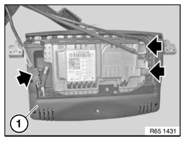
Fig. 132: Removing Plug Connection And Monitor
REMOVING AND INSTALLING/REPLACING TRIM FOR REAR MONITOR DISPLAY AT REAR
IMPORTANT: Read and comply with NOTES on protection against electrostatic damage (ESD protection).
Necessary preliminary work
- REMOVE REAR MONITOR
Release screws (1).
Tightening torque 65 50 1AZ.
Remove cover (3) from rear monitor (4), unclipping plug (2) and feed out cable.
Installation note: Make sure cover (3) is correctly seated on rear monitor (4).
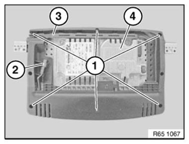
Fig. 133: Identifying Screws, Cover, Unclip Plug And Rear Monitor
READ NEXT:
 Audio, Navigation And Information Systems
KNIFE
Knife MW
Note: (Cutting knife set for roof-mounted aerial (empty housing) ) special
tool for manual operation only. 65 2
011 Drawing knife with plastic sleeve; 65 2 012 Pull handle with plastic
SEE MORE:
Controls
Parking Brake Button
The parking brake button supplies the EMF control unit with the button
operation signal. The signal is
duplicated on the parking brake button and transmitted to the EMF control unit
via double direct wired
connections. It not only enables the EMF control unit to distinguish be
Safety belts- Correct use of safety belts
Wear the safety belt twist-free and tight to
your body over your lap and shoulders.
Wear the safety belt deep on your hips over
your lap. The safety belt may not press on
your stomach.
Do not rub the safety belt against sharp
edges, or guide it or jam it in across hard or
fragile objects.
