BMW 7 Series: Audio, Navigation And Information Systems
KNIFE
Knife MW
Note: (Cutting knife set for roof-mounted aerial (empty housing) ) special tool for manual operation only. 65 2 011 Drawing knife with plastic sleeve; 65 2 012 Pull handle with plastic sleeve, 65 2 013. Special blade is replaced by 65 2 014 Special blade
SI number
01 15 08 (475)
Consisting of:
2 = 0495112 Handle
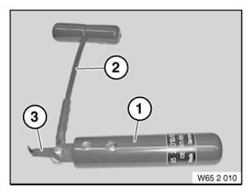
Fig. 1: Identifying Knife (652010)
NOTE: (Pull handle)
1 = 0495113 Handle
NOTE: (Drawing knife with plastic sleeve)
3 = 0495114 Blade
NOTE: (Special blade) Replaced by 65 2 014 (0496 531)
4 = 0496531 Blade
NOTE: (Special blade) Replaced by special tool 65 2 013 since 08/2008.
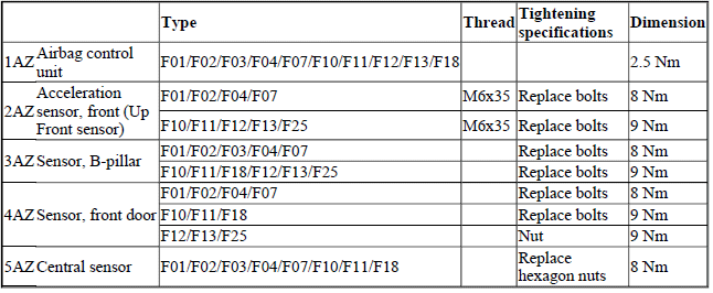
AIRBAG TRIGGERING CONTROL
TIGHTENING TORQUE SPECIFICATION - AIRBAG TRIGGERING CONTROL
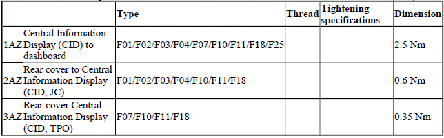
CENTRAL INFORMATION DISPLAY (CID)
TIGHTENING TORQUE SPECIFICATION - CENTRAL INFORMATION DISPLAY (CID)
PEDESTRIAN PROTECTION
TIGHTENING TORQUE SPECIFICATION - PEDESTRIAN PROTECTION

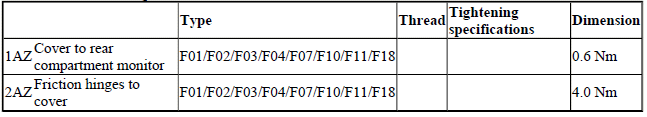
REAR-COMPARTMENT MONITOR
TIGHTENING TORQUE SPECIFICATION - REAR-COMPARTMENT MONITOR
READ NEXT:
 Adjusting Gear Lever (Parking Lock Emergency Release)
NOTE: Check cable for ease of movement.
Move gear selector switch to "P" position.
Control for emergency release must not be actuated.
Unfasten nut.
Disconnect cable (1).
Installation:
Release nu
SEE MORE:
Workshop Equipment
Minimum workshop equipment requirements in order to ensure the correct and
expert performance of body
repairs:
The tools listed below must be used.
All repair stages:
TOOL SPECIFICATION
Repair stage 1:
TOOL SPECIFICATION
Repair stage 2:
TOOL SPECIFICATION
Repair stage 3:
TOOL SPECIFICATION
IMP
Remote Control Parking- System limits
Safety information
Warning
The system is designed to operate in certain
conditions and circumstances. Due to conditions
or other factors, the system may not respond.
There may be a risk of accident or risk
of damage to property. Actively intervene as
warranted. Refer to the information in this Own
