BMW 7 Series: Venting And Filling Cooling System With Vacuum Filling Unit
Notes
IMPORTANT: Lifetime coolant filling:
Never reuse used coolant! When replacing and removing components which rely on the corrosion protection effect of the coolant, it is essential to change the coolant. The cooling system must therefore be drained and refilled.
In the case of other removal work involving the draining of partial quantities of coolant, replace these quantities which have been drained with new coolant.
IMPORTANT: You must protect the alternator against contamination by coolant when carrying out repair work on the cooling circuit.
Cover alternator with suitable materials.
Failure to comply with this procedure may result in an alternator malfunction.
Note on ordering:
- Workshop equipment
- Workshop equipment catalogue
- No.- 81 39 152 473
IMPORTANT: Risk of slipping due to coolant on the floor.
Risk of injury!
Catch and dispose of emerging coolant in drip tray (1) and if necessary special tool 00 2 030 (universal hydraulic lifting equipment).
Recycling
Observe country-specific waste disposal regulations.
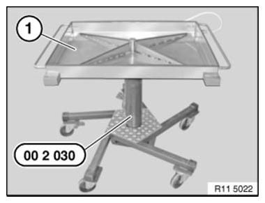
Fig. 15: Lifting Of Drip Tray Using Special Tool (00 2 030)
Graphic shows the N63, procedure for other engines identical.
IMPORTANT: Check all the coolant hoses before filling the cooling system with the vacuum filling unit.
If necessary, replace damaged and porous coolant hoses.
Vacuum filling unit consists of
- Filling unit with vacuum meter and shutoff valves
- Filler hose
- Coolant container
- Venturi nozzle
- Compressed air connection (max. 6 bar)
- Outgoing-air hose (lead outgoing-air hose into a collecting container)
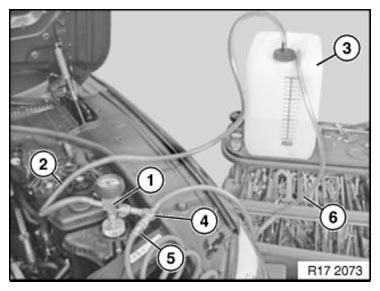
Fig. 16: Identifying Vacuum Filling Unit
Preconditions
- Cooling system expansion tank must be empty.
- There must be sufficiently premixed coolant in the filling unit
container, 1 - 2 liters more than the vehicle
filling capacity.
- Use only recommended coolant and observe mixture ratio.
- Observe FILLING CAPACITIES.
- Position the filling unit container at the same height as the coolant expansion tank.
- Compressed-air connection with 6 bar pressure present.
- Set heating to maximum temperature.
Application
Connect filling unit (1) with adapter (2) 17 0 113 to coolant expansion tank.
Shutoff valves (A) and (B) must be closed.
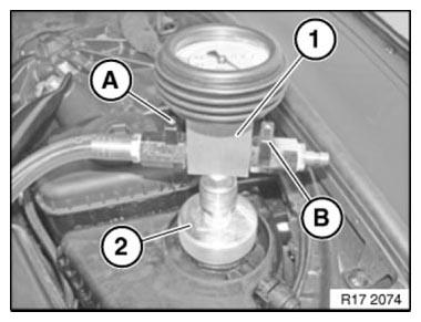
Fig. 17: Identifying Coolant Filling Unit With Adapter And Shut-Off Valves
Connect venturi nozzle (1) to filling unit (2).
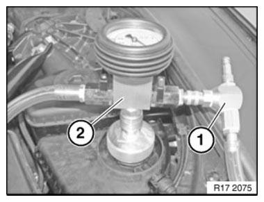
Fig. 18: Identifying Coolant Filling Unit With Venturi Nozzle
Connect compressed air (1) and open shutoff valve (B).
The venturi nozzle produces a flow noise.

Fig. 19: Identifying Shut-Off Valve With Compressed Air Line
Then open shutoff valve (A) until the filling hose (1) is free of bubbles. Close shutoff valve (A) again. The filling hose (1) is vented in this way.
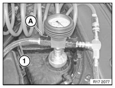
Fig. 20: Identifying Coolant Filling Hose With Shut-Off Valve
Shutoff valve (B) remains open. Approx. 1 minute. Generate vacuum in cooling circuit. The final vacuum is reached at a vacuum of -0.7 to -0.95 bar. Green scale on the vacuum meter.
NOTE: The coolant hoses contract during vacuum build-up.
Then close shutoff valve (B) again.
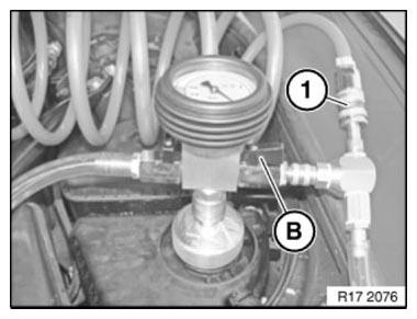
Fig. 21: Identifying Coolant Shut-Off Valves
Both shutoff valves (A) and (B) must be closed. Then seal Venturi nozzle (1).
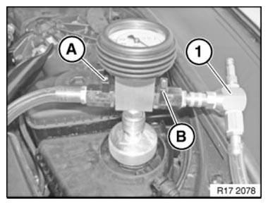
Fig. 22: Identifying Venturi Nozzle With Shut Off Valves
The cooling system must hold the vacuum for 30 seconds. If the needle in the vacuum meter falls, this indicates a leak in the cooling system.
If the vacuum remains constant, proceed with filling.
In the event of leaks, check COOLING SYSTEM FOR LEAKS.
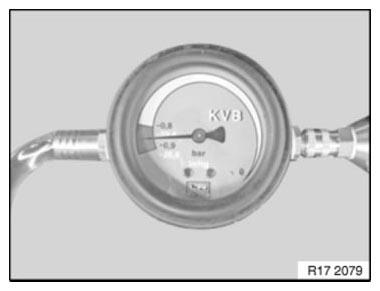
Fig. 23: Checking Cooling System For Leaks
IMPORTANT: There must be sufficiently PREMIXED COOLANT in the filling unit container, 1 - 2 liters more than the vehicle filling capacity.
Position the filling unit container at the same height as the coolant expansion tank.
Shutoff valve (B) remains closed during the filling process.
To fill the cooling system, open shutoff valve (A) to filling unit container.
Coolant is now added.
The filling process is finished when the needle in the vacuum meter is at 0 bar or no longer falls.
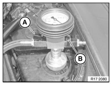
Fig. 24: Identifying Cooling System Shut-Off Valves
If necessary, reduce remaining vacuum. Open shutoff valve (B) to do so.
Remove filling unit with adapter from expansion tank.
Adjust coolant level to max.
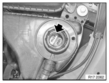
Fig. 25: Adjusting Coolant Level To Maximum
Close coolant expansion tank.
Installation note: Close the sealing cap (1) until the arrows line up.
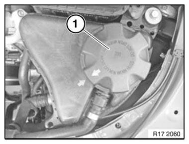
Fig. 26: Identifying Coolant Expansion Tank Sealing Cap
Check function of cooling system.
Check COOLING SYSTEM FOR LEAKS.
READ NEXT:
 Venting Cooling System For Intercooler (N63)
Notes
WARNING: Danger of scalding!
Open sealing cap only after engine has cooled down.
IMPORTANT: Cooling system for intercooler has a separate cooling circuit.
Coolant is added at intercooler expans
Radiator, Expansion Tank, Pipes
CHECKING COOLING SYSTEM FOR WATERTIGHTNESS (N54, N63)
Notes
WARNING: Risk of scalding!
Only perform this repair work after engine has cooled down.
Protective measures/rules of conduct
Wear safety go
SEE MORE:
Instructions For Opening And Replacing Parts In Refrigerant Circuit
WARNING:
Avoid contact with refrigerant and refrigerant fluid
Follow safety information for handling R134A refrigerant.
Follow safety information for HANDLING REFRIGERANT FLUID
IMPORTANT:
Always use new O-rings each time A/C connections are opened (refer to
Electronic Parts Catalogue)
They
Introduction
BMW Steering Systems - Innovative and technically always something special
Since the introduction of the first EPS electric power steering system on the
E85 in 2002, the variety of
technical innovations on steering systems has rapidly expanded. Before then the
following systems were used:
Hydrau
