BMW 7 Series: Removing And Installing/Replacing Airbag Control Unit
IMPORTANT: Read and comply with NOTES on protection against electrostatic damage (ESD protection)!
WARNING: NOTE AIRBAG SAFETY INSTRUCTIONS! Incorrect handling can activate airbag and cause injury.
Necessary preliminary tasks
- F01/02: Clamp off BATTERY NEGATIVE LEAD
- F03Remove both negative battery cables
- Remove UPPER INSTRUMENT PANEL STORAGE COMPARTMENT
- Remove trim for instrument panel, bottom left.
Release screw (1).
Tightening torque 65 77 1AZ.
Press airbag control unit (2) in direction of arrow out of rubber mounts (3).
Feed out airbag control unit (2) towards bottom.
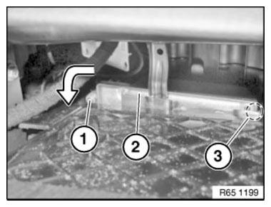
Fig. 109: Identifying Screw And Airbag Control Unit
Unlock plug connections (1) and (2) on airbag control unit (3) and disconnect.
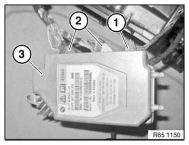
Fig. 110: Identifying Plug Connections And Airbag Control Unit
Installation
Make sure guides (1) are correctly seated in rubber mount (2).
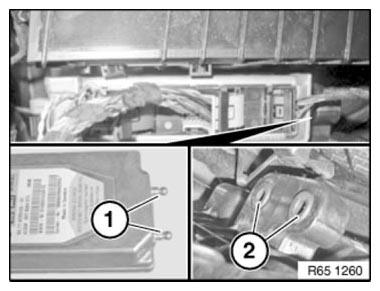
Fig. 111: Identifying Guides And Rubber Mount
Replacement
Carry out VEHICLE PROGRAMMING/ENCODING.
REMOVING AND INSTALLING/REPLACING CENTRAL SENSOR
WARNING: Note AIRBAG SAFETY INSTRUCTIONS ! Incorrect handling can activate airbag and cause injury.
Necessary preliminary tasks
- Clamp off BATTERY NEGATIVE LEAD
- Remove COMPLETE CENTRE CONSOLE
Unscrew nuts (1).
Remove holder (2) from center console wiring harness (3).
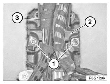
Fig. 112: Identifying Nuts, Holder And Centre Console Wiring Harness
Unscrew nuts (1).
Tightening torque 65 77 5AZ.
Remove sensor (2).
Unlock plug connection (3) and disconnect.
Installation: Make sure sensor is mounted without play.
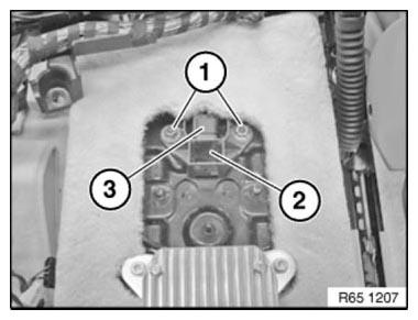
Fig. 113: Identifying Nuts, Sensor And Plug Connection
REMOVING AND INSTALLING/REPLACING EMERGENCY POWER SIREN WITH TILT SENSOR
Necessary preliminary work
- Remove GUIDE FOR BUMPER AT REAR RIGHT
Secure guide for bumper (3) against falling out.
Unfasten plug connection (1) and disconnect.
Slacken nut (1).
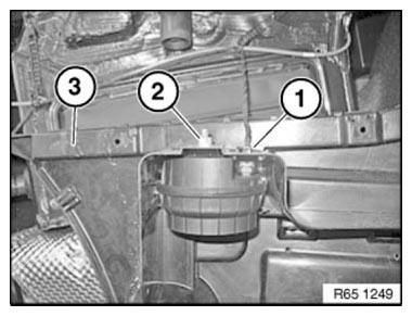
Fig. 114: Identifying Bumper, Plug Connection And Slacken Nut
Unlock catch (1).
Remove emergency power siren (2) from guide for bumper (3).
Catch (1) must not be damaged.
Make sure emergency power siren (2) is correctly seated on guide for bumper (3).
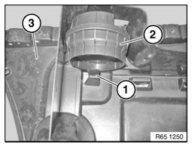
Fig. 115: Identifying Catch, Bumper And Power Siren
Replacement
Carry out VEHICLE PROGRAMMING/ENCODING.
REMOVING AND INSTALLING/REPLACING FRONT LEFT SENSOR (US VERSION ONLY)
Necessary preliminary tasks
- Remove FRONT LEFT WHEEL ARCH COVER
NOTE: This work step varies according to engine type.
Release screw (1) on auxiliary radiator bracket (2).
Remove holder (2) and carefully place to one side.
Installation
Holder (2) must be correctly seated in the designated guides.
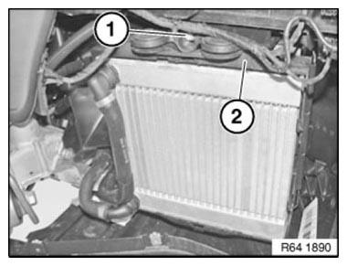
Fig. 116: Identifying Screw, Holder And Bracket
Release screws (1) on lock carrier (2).
Tightening torque 65 77 2AZ.
Feed out sensor (3).
Unfasten plug connection (2) and disconnect.
Installation: Make sure sensor (3) is in correct installation position.
Sensor surface must point upwards.
Plug connection (2) must point in opposite direction to direction of travel.
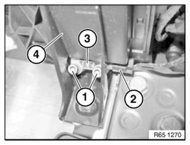
Fig. 117: Identifying Screws, Lock Carrier, Plug Connection And Sensor
REMOVING AND INSTALLING/REPLACING FRONT RIGHT SENSOR (US VERSION ONLY)
Necessary preliminary tasks
- Remove FRONT RIGHT WHEEL ARCH TRIM
NOTE: This operation depends on the engine version.
Release screw (1) on auxiliary radiator bracket (2).
Remove auxiliary radiator bracket (2) and carefully place to one side.
Installation: Auxiliary radiator bracket (2) must be correctly seated in the designated guides.
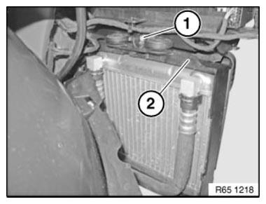
Fig. 118: Identifying Screw And Auxiliary Radiator Bracket
Release screws (1).
Tightening torque 65 77 2AZ.
Feed out acceleration sensor (2).
Unlock plug connection (3) and disconnect.
Installation: Make sure acceleration sensor (2) is in correct installation position.
Sensor surface of acceleration sensor (2) must point upwards! Plug connection (3) must point in opposite direction to direction of travel.
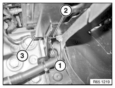
Fig. 119: Identifying Screws, Acceleration Sensor And Plug Connection
READ NEXT:
 Removing And Installing/Replacing Middle Pedestrian Protection Sensor
WARNING: Observe SAFETY INSTRUCTIONS for handling gas generators.
Incorrect handling can activate pedestrian protection and cause injury.
Necessary preliminary work
Disconnect BATTERY CABLE
Remove
Car Communication Computer (CCC)
REMOVING AND INSTALLING (REPLACING) CAR INFORMATION COMPUTER (CIC)
IMPORTANT: Risk of damage!
A hard disk is installed in the Car Information Computer (CIC).
Carry out mechanical work on the CIC and
Audio, Navigation And Information Systems
KNIFE
Knife MW
Note: (Cutting knife set for roof-mounted aerial (empty housing) ) special
tool for manual operation only. 65 2
011 Drawing knife with plastic sleeve; 65 2 012 Pull handle with plastic
SEE MORE:
Low Beam Headlight
To switch on the low beam headlights, the light switch in the lights control
panel must be turned to low beam
headlight (switch position 2) When the low beam headlights are switched-on the
bi-xenon headlights are
activated.
After turning off the engine, the side lights stay on although the light
Repairing Airbag Cables
IMPORTANT: Only repair those cables which show visible signs of damage. In
the event of
visible damage, make sure there is only one cable repair in effect after the
repair work. If no visible damage can be identified, the entire cable must be
replaced. When carrying out repairs to the airbag wiring
