BMW 7 Series: Replacing Roof Outer Skin (Version With Slide/tilt Sunroof)
Read contents of BODY, GENERAL.
STRIP DOWN VEHICLE
NOTE: Observe new procedure for bonding and riveting (REPAIR STAGE 2).
Following parts are required:
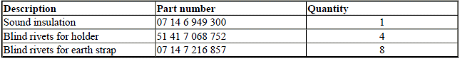
- Roof outer skin
Additional required parts (not pictured):
PART SPECIFICATION
Following consumables are required:
MATERIAL CHART
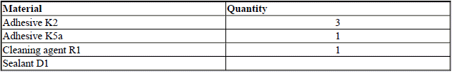
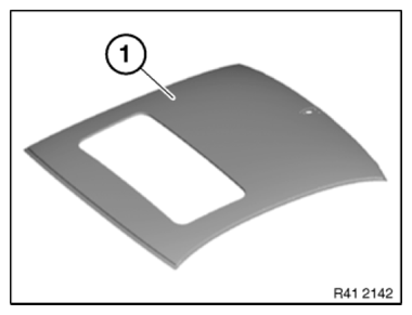
Fig. 289: Identifying Roof Outer Skin
Tools also required:
- Roof pliers set, order number: 81 43 2 158 707
NOTE: Store adhesive at room temperature.
Adhere to adhesive processing temperature of 15 - 28ºC without fail.
Prior to installation, store roof outer skin and vehicle for at least 12 hours at room temperature (17ºC to 35ºC).
Removing roof outer skin
View of passenger compartment above driver's seat.
Operation is described on the left side. Right side identical.
Release screw (1).
Release rivets (2) and remove holder (3).
Fig. 290: Identifying Rivets, Screw And Holder
Release rivets (2) and remove earth strap (2).
NOTE: Do not damage earth strap.
Replace if necessary, part number 61 12 7 213 377
Also release earth straps on left and right above rear seat.
IMPORTANT: Only the special rivets may be used to fit the earth straps!
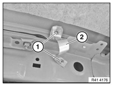
Fig. 291: Identifying Rivets And Earth Strap
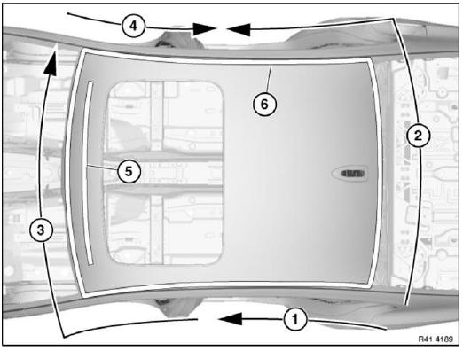
Fig. 292: Identifying Bonded Connection
Heat bonded connection (6) with hot air blower until adhesive is loosened, then release.
In so doing, proceed in sections (1 to 4), starting at rear left.
Heat bonded connection (5) from passenger compartment and release.
IMPORTANT: Extract vapors and gases.
Primed surface must not be damaged.
Do not use any metallic tools.
Carefully drive in plastic or wooden wedge (1) at heated section. The wedge creates tension between roof outer skin and body.
IMPORTANT: Do not exert force to drive in wedge. If the wedge cannot be driven in, continue heating roof outer skin on adhesive flange over a large area (max. 180ºC).
Carry out operation with a 2nd person helping.
Heat next section until roof outer skin has detached from body. Reapply plastic wedge. Repeat procedure until roof outer skin is completely detached.
Take off roof outer skin.
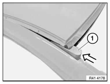
Fig. 293: Taking Off Roof Outer Skin
Installing roof outer skin
Remove adhesive residues (1) to 0.5 mm.
Primed surface must not be damaged.
Smaller damage to 5 mm or scratch marks can be ignored.
In the event of larger damage to primer (greater than 5 mm), proceed as follows:

Fig. 294: Identifying Roof Outer Skin Adhesive Residues
In the event of larger damage to primer, the following procedure applies: Clean damaged area with cleaning agent R1.
Apply adhesive K5a to the bare areas with a spatula or a brush. Apply a uniformly thin layer (max. 0.5 mm).
The roof outer skin can be bonded after a curing period of 24 hours.
The adhesive flange area must not be painted over when the roof frame is being repaired or replaced.
Fit new sound insulation in areas (1).
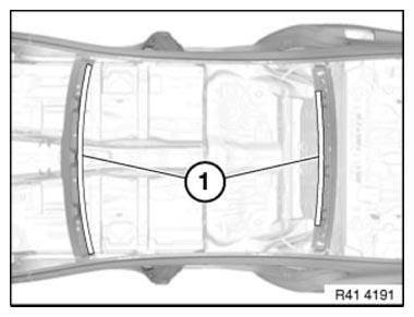
Fig. 295: Identifying Sound Insulation Areas
Clean bonding surfaces (1) on body and on new part with cleaning agent R1. Observe an air drying time of 2 minutes.

Fig. 296: Identifying Bonding Surfaces On Body
Lay out following parts ready:
- Adhesive in adhesive gun and two further glue cartridges.
- Rear window
- Roof trim strips
- Preset roof pliers with tensioning straps
- 3 large fixing pliers (windscreen area)
- 3 small fixing pliers (rear window area)
Steps 1 to 3 described below must be completed within 15 minutes!
- Applying adhesive
- Joining and fixing roof outer skin
- Applying adhesive to nodes on A- and C-pillars. Removing excess adhesive.
NOTE: To ensure that the processing time of 15 mins. is observed, make sure that the clamping tools are pre-adjusted. To do so, lay on roof outer skin without adhesive.
Then mount and adjust all clamping tools. In so doing, position roof pliers close to roof frame. (For arrangement see Fig. 283)
IMPORTANT: Position roof pliers only in areas of stiffening impressions.
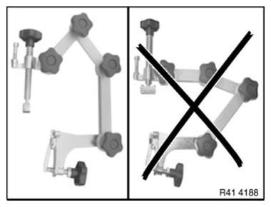
Fig. 297: Identifying Correct Position Of Roof Pliers
1. Applying adhesive
Apply K2 adhesive in areas (1).
Guide nozzle at an angle of max. 60º along adhesive flange.
Cross-section of adhesive bead approx. 4 - 5 x 10 mm.
Apply a short reference bead at an appropriate point for later checking.
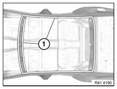
Fig. 298: Identifying K2 Adhesive Area
Apply a little more adhesive K2 to nodes (1) of A-and C-pillars.
NOTE: Excess material is later used for spreading to side frame.
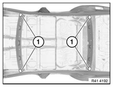
Fig. 299: Identifying A And C-Pillars Adhesive K2 Applying Area
Apply a little less adhesive (1) in area of holders (1).
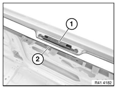
Fig. 300: Identifying Adhesive Area And Holders
2. Joining and fixing roof outer skin
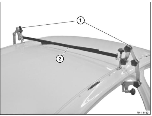
Fig. 301: Securing Roof Pliers With Tensioning Strap
Place roof outer skin with 3 helpers evenly and centrally on vehicle.
Fit rear window and roof trim strips to check correct position of roof outer skin.
Mount roof pliers (1) and secure with tensioning strap (2).
IMPORTANT: Position clamping tools only on stiffening impressions (1) in adhesive flange area of roof outer skin.
This ensures that correct distance and thus the correct amount of adhesive between the roof outer skin and the roof frame.
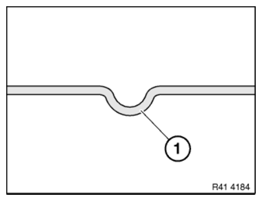
Fig. 302: Identifying Roof Outer Skin Adhesive Flange Area
Secure roof outer skin at 3 areas with roof pliers and tensioning straps.
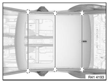
Fig. 303: Identifying Roof Outer Skin Securing Areas
Secure roof outer skin in windscreen area 3 times with large fixing pliers (1).
In rear window area use small fixing pliers (2) 3 times.
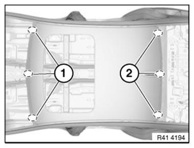
Fig. 304: Identifying Roof Outer Skin Securing Area In Windscreen
IMPORTANT: Risk of damage! Use a suitable support (1) (approx. 50 x 50 mm) in windscreen area, as otherwise roof pillar (2) may be pressed in.
(3) Roof outer skin
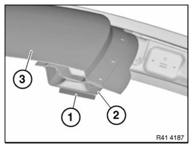
Fig. 305: Identifying Support, Roof Pillar And Roof Outer Skin
3. Applying adhesive to nodes on A- and C-pillars. Removing excess adhesive
Adjust stage (1) between roof outer skin (2) and A-pillar or roof outer skin (2) and C-pillar with emerged adhesive. Remove excess adhesive.
IMPORTANT: Never use cleaning agents!
Do not leave any traces of sharp edges as this could compromise the tightness of the subsequent bond.
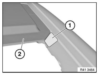
Fig. 306: Identifying Stage And Roof Outer Skin
Spread excess adhesive in roof trim strip channel. Mounting surfaces of clips for roof trim strips must not be moistened with adhesive.
Clamping tools must remain on the vehicle for at least 1 hour. Do not move the vehicle during this period. Only then is it permitted to proceed with subsequent installation work.
Check whether reference bead has hardened after 2 hours hardening time (15-38ºC).
After bonding, the vehicle must remain parked for at least 12 hours at room temperature (15-38ºC).
The vehicle is then ready for operation.
STRIPPING OPERATIONS - REPLACING ROOF OUTER SKIN (VERSION WITH SLIDE/TILT SUNROOF)
NOTE: Owing to the different engine variants and equipment specifications, not all the components are taken into consideration.
The following list basically represents the removal sequence.
- Remove left roof trim strip (job number: 51 13 280)
- Remove right roof trim strip (job number: 51 13 280)
- Remove cowl panel cover (job number: 51 13 116)
- Remove both door post trim panels (job number: 51 43 148)
- Remove both rear roof pillar trim panels (job number: 51 43 251)
- Remove both front roof pillar trim panels (job number: 51 43 201)
- Remove headlining (job number: 51 44 011)
- Remove slide/tilt sunroof (FR number: 54 12 211)
- Remove front windscreen (job number: 51 31 000)
- Remove rear window (job number: 51 31 200)
- Remove roof aerial (job number: 65 20 035)
- Partially detach edge protector
- Remove both head restraints
STRIPPING OPERATIONS - REPLACING ROOF OUTER SKIN (VERSION WITHOUT SLIDE/TILT SUNROOF)
NOTE: Owing to the different engine variants and equipment specifications, not all the components are taken into consideration.
The following list basically represents the removal sequence.
- Remove left roof trim strip (FR number: 51 13 280)
- Remove right roof trim strip (FR number: 51 13 280)
- Remove cowl panel cover (FR number: 51 13 116)
- Remove both covers for door posts (FR number: 51 43 148)
- Remove both covers for roof pillars, rear (FR number: 51 43 251)
- Remove both covers for roof pillars, front (FR number: 51 43 201)
- Remove headlining (job number: 51 44 001)
- Remove front windscreen (FR number: 51 31 000)
- Remove rear window (FR number: 51 31 200)
- Remove roof aerial (FR number: 65 20 035)
- Partially disengage edge protection
- Remove both head restraints
READ NEXT:
 Replace The A-Pillar On The Outside Left In The Area Of The
Windscreen
Replace The A-Pillar On The Outside Left In The Area Of The
Windscreen
Read contents of BODY, GENERAL.
Remove or cover those vehicle components in the repair area which are
susceptible to heat or dust.
Use only approved SPOT-WELDING APPARATUS for repairs.
IMPORTANT: O
Replacing Front Left Door Post (Front Side Panel Removed)
Procedure OBSERVE repair stage 3! Read contents of BODY, GENERAL.
Spot-weld bonding is used on this vehicle. Observe specific procedure See
SPOT-WELD BONDING
STEEL PARTS.
Place vehicle on straighte
SEE MORE:
Output Shaft
NOTES ON REMOVING AND INSTALLING LOW PROFILE BAND CLAMPS
Notes
IMPORTANT: During removal Low Profile band clamp (dotted line) is
overstretched and must
not be reused!
Fig. 82: Identifying Low Profile Band Clamp (Dotted Line)
Removing
Place special tool 31 5 200 on tabs (1, 2).
NOTE: Make sure that
Components
Active Roll Stabilization (ARS)
Control Unit
The VDM control unit is located in the passenger compartment near the
right-hand A-pillar. The VDM control
unit receives its power supply via Terminal 15N and is protected by a 5A fuse.
The VDM control unit is
activated exclusively by the Car Access Sys
