BMW 7 Series: Replacing Engine Support In Front Of Wheel Arch, Left
Observe procedure of REPAIR STAGE 3.
Read CONTENTS OF BODY, GENERAL.
Steel-aluminium composite construction is used on the vehicle.
Observe specific procedures for OPENING ADHESIVE BONDS, BONDING ALUMINIUM ON STEEL, and OPENING RIVETED JOINTS.
Use only approved spot-welding apparatus for repairs. See WORKSHOP EQUIPMENT.
Place vehicle on straightening bench.
Necessary preliminary work:
Remove CARRIER SUPPORT
Following new body parts are required (refer to BMW Electronic Parts Catalogue):
- Engine support, front
.png)
Fig. 99: Identifying Front Engine Support
Mark severance cut in accordance with Dimension a and cut.
Dimension a=40 mm before wheel arch edge.
Remove section of engine support.
Installation note:
Mark severance cut on new part in accordance with vehicle and cut.
Adjust new part to fit with alignment bracket or universal mount.
Weld in REINFORCEMENT PLATE at severance cut.
.png)
Fig. 100: Identifying Welding Area
REPLACING ENGINE SUPPORT WITH WHEEL ARCH, LEFT
Procedure OBSERVE repair stage 3! Read contents of BODY, GENERAL.
Steel-aluminium composite construction is used on the vehicle.
Spot-weld bonding is used on this vehicle. Observe specific PROCEDURE.
Place vehicle on straightening bench.
Following new body parts are required:
- Engine support
- Engine support, rear
- Wheel arch, front
- Connection, wheel arch/entrance
- Connection, side frame, rear
- Shaped parts, carrier support, wheel arch, front (not shown)
.png)
Fig. 101: Identifying Engine Support, Rear Side Frame Connection And Wheel
Arch/Entrance
Connection
Open welded connections in area (1).
.png)
Fig. 102: Identifying Welded Connections Area
Open welded connections in area (1).
.png)
Fig. 103: Identifying Welded Connections Area
LOOSEN spot-welded adhesive joints in area (1).
Open welded connections in area (2).
Roughly cut side frame connection (3) along lines (4).
Remove side frame connection (3).
Installation note: MAG weld new part in areas (4).
To do so, apply 10 mm long fillet welds at spacing of 15 mm.
.png)
Fig. 104: Identifying Side Frame Connection And Welded Connections Area
Open welded connections in area (1).
Installation note: Replace CAVITY SEALING (2).
.png)
Fig. 105: Identifying Welded Connections Area And Cavity Sealing
Mark severance cut (1) in accordance with dimension a and cut engine support.
Dimension a = 140 mm Installation note: Weld in REINFORCEMENT PLATE at severance cut.
.png)
Fig. 106: Identifying Reinforcement Plate Severance Cut
Drill out rivet connections in area (1).
Open BONDED CONNECTIONS in area (1).
Remove wheel arch (2) with engine support.
Installation note: Use 6 N2 RIVETS in area (1).
Glue new part with ADHESIVE K1.
.png)
Fig. 107: Identifying Bonded Connections Area And Wheel Arch
Open welded connections in area (1).
Remove metal section (2).
.png)
Fig. 108: Identifying Welded Connections Area And Metal Section
Mark severance cut (1) and cut.
IMPORTANT: Cut outer panel only.
Open welded connections in area (2).
.png)
Fig. 109: Identifying Outer Panel Severance Cut And Welded Connections Area
View of engine support from front.
Open welded connections in area (1).
.png)
Fig. 110: Identifying Front Engine Support Welded Connections Area
Open welded connections in area (1).
Remove metal section (2).
.png)
Fig. 111: Identifying Welded Connections Area And Metal Section
Preparation of new part
Open welded connections in areas (1). Remove metal section (2).
.png)
Fig. 112: Identifying Welded Connections Areas And Metal Section
Preparation of new part
Mark severance cut (1) in accordance with dimension a and cut.
Dimension a = 20 mm
.png)
Fig. 113: Identifying Part Cutting Dimension
Preparation of new part
Mark rear engine support in accordance with severance cut on vehicle and cut (1).
.png)
Fig. 114: Identifying Rear Engine Support Cutting Mark
Installation note: Mark severance cut (1) in accordance with dimension a and cut.
Dimension a = 15 mm Remove metal section (2).
.png)
Fig. 115: Identifying Metal Section Cutting Dimension
IMPORTANT: To avoid contact corrosion, do not grind the new wheel arch part in the area of the BONDING SURFACES.
Grind bonding surfaces on body blank.
Clean bonding surfaces with cleaning agent R1.
Installation note:
Adjust new parts to fit with alignment bracket or universal mounting.
Drill new rivet holes in areas (1) and (2).
Deburr bore holes.
Use 19 N2 rivets.
Glue new part with adhesive K1.
.png)
Fig. 116: Identifying Rivet Holes Drill Areas
View from below.
Installation note:
Weld new components in area (1) additionally.
.png)
Fig. 117: Identifying New Components Welding Area
Installation note:
Weld new components in area (1) additionally.
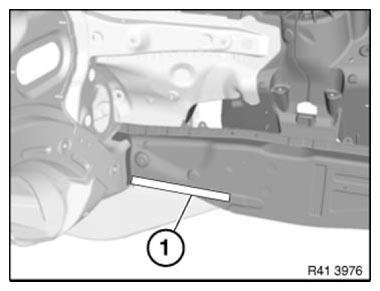
Fig. 118: Identifying New Components Welding Area
Installation note:
Weld new component in area (1) additionally.
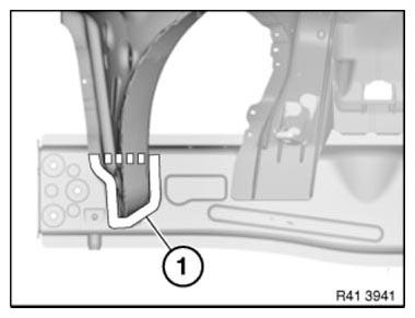
Fig. 119: Identifying New Components Welding Area
Installation note:
MAG-weld new component in area (1) additionally.
To do so, apply 2 fillet welds at distance of approx. 20 mm. Length of fillet welds approx. 10 mm.
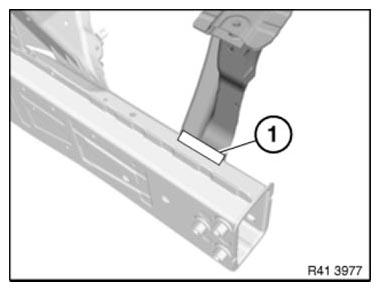
Fig. 120: Identifying New Component MAG-Welding Area
READ NEXT:
 Replacing Engine Support/Front Left Side Frame Connection (Front
Left Wheel Arch Removed)
Replacing Engine Support/Front Left Side Frame Connection (Front
Left Wheel Arch Removed)
Observe procedure for REPAIR STAGE 3.
Read contents of BODY, GENERAL.
To remove engine support side frame connection
Following new body parts are required:
Connection, wheel arch/entrance
Fig. 12
Replacing Front Section Of Left Engine Support
Observe procedure of REPAIR STAGE 3.
Read contents of BODY, GENERAL.
Steel-aluminium composite construction is used on the vehicle.
Observe specific procedure.
Use only approved SPOT-WELDING APPAR
Replacing Entrance With Door Post, Left And Right (Partial
Replacement, B-pillar)
Observe procedure of REPAIR STAGE 3.
Read CONTENTS OF BODY, GENERAL.
Spot-weld bonding is used on this vehicle. Observe specific PROCEDURE.
Use only approved spot-welding apparatus for repairs.
Pl
SEE MORE:
System Overview
Schematic System Circuit Diagram - Interior Lighting
The system circuit diagram follows the description below and provides an
overview of the full extent of all
possible interior lighting options.
The status of the door contact (Hall sensor) in the lock (38) changes, for
example, when the door is
Removing And Installing/Replacing Left Or Right Rear Brake
Caliper
Necessary preliminary tasks
Remove WHEEL
Read and comply with GENERAL INFORMATION.
After completing work: replace fluid in brake system.
Press clutch pedal down to floor and secure with pedal support.
NOTE: The pedal support may only be released when the brake lines are
reconnected.
This preve
