BMW 7 Series: Replacing Front Section Of Left Engine Support
Observe procedure of REPAIR STAGE 3.
Read contents of BODY, GENERAL.
Steel-aluminium composite construction is used on the vehicle.
Observe specific procedure.
Use only approved SPOT-WELDING APPARATUS for repairs.
Place vehicle on straightening bench.
Following new body parts are required:
- Engine support
- Engine support, rear
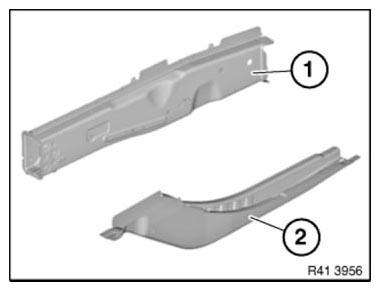
Fig. 126: Identifying Engine Support And Engine Support, Rear
Open welded connections in area (1).
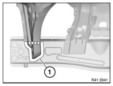
Fig. 127: Identifying Welded Connections Area
Drill out riveted connections in areas (1) and (2).
Installation note: Use 19 N2 RIVETS in areas (1) and (2).
Glue new component with ADHESIVE K1.
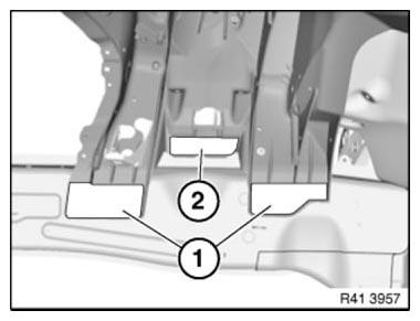
Fig. 128: Identifying Rivet Holes Drill Areas
Mark severance cut (1) in accordance with dimension a and cut engine support.
Measurement a=140 mm
Installation note: Weld in REINFORCEMENT PLATES at severance cut.
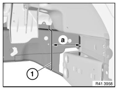
Fig. 129: Identifying Reinforcement Plate Severance Cut
Roughly mark severance cuts (1) and cut.
IMPORTANT: Do not damage spring strut dome (2).
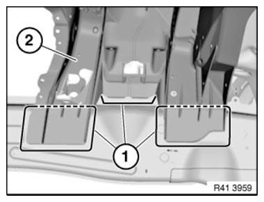
Fig. 130: Identifying Spring Strut Dome And Severance Cuts
Heat ADHESIVE AREAS with hot air blower and release sheet sections (1) from spring strut dome.
IMPORTANT: Do not damage spring strut dome (2).
Installation note: Remove adhesive residue from spring strut dome.
Then FLAME-COAT bonding surfaces of spring strut dome.
Grind bonding surfaces on engine support blank.
Clean bonding surfaces with CLEANING AGENT R1 !
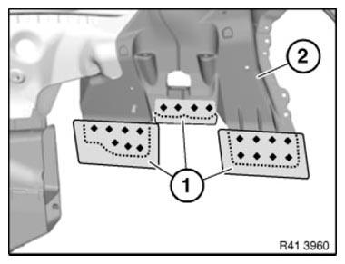
Fig. 131: Identifying Sheet Sections And Spring Strut Dome
Open welded connections in area (1) and remove engine support section (2).
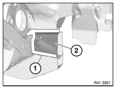
Fig. 132: Identifying Welded Connections Area And Engine Support Section
Installation note: MAG-weld new part in area (1).
To do so, apply 2 fillet welds at spacing of 15 mm.
Length of fillet welds approx. 10 mm.
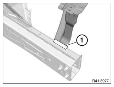
Fig. 133: Identifying New Component MAG-Welding Area
Preparation of new part
Mark new parts in accordance with severance cuts on vehicle and cut.
Installation note: Adjust new parts to fit with alignment bracket or universal mounting.
READ NEXT:
 Replacing Entrance With Door Post, Left And Right (Partial
Replacement, B-pillar)
Replacing Entrance With Door Post, Left And Right (Partial
Replacement, B-pillar)
Observe procedure of REPAIR STAGE 3.
Read CONTENTS OF BODY, GENERAL.
Spot-weld bonding is used on this vehicle. Observe specific PROCEDURE.
Use only approved spot-welding apparatus for repairs.
Pl
Replacing Outer Section Of Left Or Right Rear Wheel Housing (Side
Panel Removed)
Read contents of BODY, GENERAL.
Spot-weld bonding is used on this vehicle. Observe specific procedure See
SPOT-WELD BONDING
STEEL PARTS.
Remove or cover those vehicle components in the repair area w
Replacing The Carrier Support Before The Wheel Arch On The Left
Follow procedure for REPAIR STAGE 3.
Read contents of BODY, GENERAL.
Remove or cover those vehicle components in the repair area which are
susceptible to heat or dust.
Use only APPROVED SPOT-WELDI
SEE MORE:
Front Axle
FRONT AXLE - RIDE HEIGHT
FRONT AXLE - RIDE HEIGHT F01/F02/REAR WHEEL
FRONT AXLE - RIDE HEIGHT AND REAR WHEEL SPECIFICATION
FRONT AXLE DIFFERENTIAL
FRONT AXLE DIFFERENTIAL F01/F02
FRONT AXLE DIFFERENTIAL SPECIFICATION
GENERAL - TRACK WIDTH / WHEELBASE
GENERAL - TRACK WIDTH/WHEELBASE F02 ALLR
GENERA
Changing wheels/tires- Jacking up the vehicle
Warning
Hands and fingers can be jammed when using
the vehicle jack. There is a risk of injury. Comply
with the described hand position and do not
change this position while using the vehicle
jack.
Hold the vehicle jack with one hand, arrow 1,
and grasp the vehicle jack crank or lever with
your
