BMW 7 Series: Replacing The Carrier Support Before The Wheel Arch On The Left
Follow procedure for REPAIR STAGE 3.
Read contents of BODY, GENERAL.
Remove or cover those vehicle components in the repair area which are susceptible to heat or dust.
Use only APPROVED SPOT-WELDING APPARATUS for repairs.
Place vehicle on straightening bench.
Following new body parts are required:
- Carrier support/basis
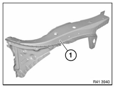
Fig. 147: Identifying Carrier Support/Basis
Open welded connections in area (1).
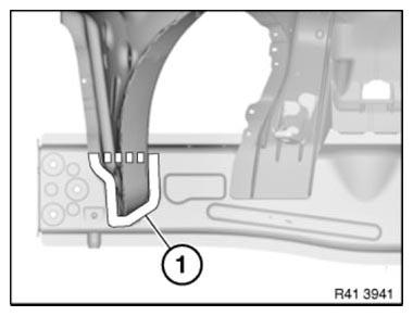
Fig. 148: Identifying Welded Connections Area
Mark severance cut (1) as pictured and cut.
IMPORTANT: Cut outer panel only.
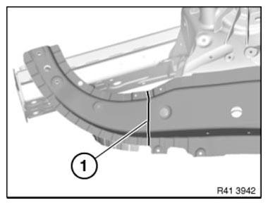
Fig. 149: Identifying Outer Panel Severance Cut
IMPORTANT: Risk of damage to spring strut dome!
Open welded connections in area (1).
Mark severance cut (2) as pictured and cut.
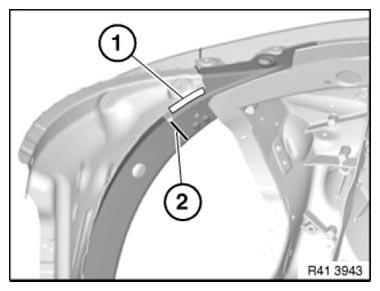
Fig. 150: Identifying Welded Connections Area And Severance Cut
Mark severance cut (1) as pictured and cut.
Remove carrier support section.
Installation note: Mark new part in accordance with body and cut.
Adjust new part to fit with alignment bracket or universal mount.
Weld in REINFORCEMENT PLATES at all severance cuts.
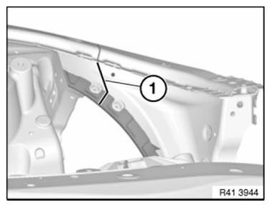
Fig. 151: Identifying Carrier Support Section Severance Cut
Installation note: MAG-weld new part in area (1).
To do so, apply 2 fillet welds at distance of approx. 20 mm. Length of fillet welds approx. 10 mm.
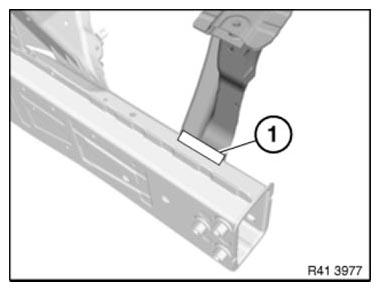
Fig. 152: Identifying New Component MAG-Welding Area
STRIPPING OPERATIONS - REPLACING FRONT LEFT WHEEL ARCH
NOTE: Owing to the different engine variants and equipment specifications, not all the components are taken into consideration.
The following list basically represents the removal sequence. Refer to the appropriate service information for each item.
- Disconnect negative battery cable
- Remove bumper trim
- Remove bumper support
- Remove headlight
- Remove radiator
- Remove A/C system condenser
- Remove and install charge air cooler
- Remove hydraulic steering cooling coil
- Remove intake silencer housing
- Remove coolant expansion tank
- Remove wheel arch cover (front section)
- Remove wheel arch cover (rear section)
- Front axle complete with engine and transmission
- Engine compartment lid seal locator
- Remove engine compartment lid
- Remove engine compartment lid hinge
- Remove left side wall
- Remove top left wishbone
- Remove left suspension brace
- Remove bulkhead sound insulation
- Remove brake booster
- Remove/detach hydraulic lines for power steering pump
- Detach coolant hoses
- Detach fuel lines
- Release left wiring harness
- Partially release/remove thermal protection
READ NEXT:
 Replace Luggage Compartment Floor And Both Side Members (Tail
Panel Trim Removed)
Replace Luggage Compartment Floor And Both Side Members (Tail
Panel Trim Removed)
Read contents of BODY, GENERAL.
STRIP DOWN VEHICLE.
Place vehicle on straightening bench.
These repair instructions comprise the procedures for REPAIR STAGE 3.
Following new body parts are require
Replacing Luggage Compartment Floor, Left Section (Tail Panel Or
Side Wall Removed)
Read contents of BODY, GENERAL.
STRIP DOWN VEHICLE
NOTE: Observe new procedure for bonding and riveting (REPAIR STAGE 2).
Following new body parts are required:
Luggage compartment floor, left Follo
SEE MORE:
Service Information
UNLOCKING THE SERVICE MENU OPTION
Several important functions can be checked directly at the CIC with the aid
of the Service menu. This menu can
be used to select and adjust settings that are not visible for the customer.
The procedure for starting the Service menu with the "safe grip" has changed
Removing And Installing/Replacing Drive For Backrest Tilt Adjustment
(Comfort Seats In Rear Compartment)
Necessary preliminary tasks
Partially remove LEFT OR RIGHT BACKREST COVER
Installation
Powerlok screws must be replaced and must not be reused
Powerlok screws are mechanical screw locks with trilobular threads
Installation
Microencapsulated screws (Loctite) must be replaced and may not be
