BMW 7 Series: Replacing Entrance With Door Post, Left And Right (Partial Replacement, B-pillar)
Observe procedure of REPAIR STAGE 3.
Read CONTENTS OF BODY, GENERAL.
Spot-weld bonding is used on this vehicle. Observe specific PROCEDURE.
Use only approved spot-welding apparatus for repairs. Place vehicle on straightening bench.
The following new body parts are required (see BMW Electronic Parts Catalogue):
- B-pillar with entrance
- ADHESIVE K1
- Blind rivets N1 (3 pieces)
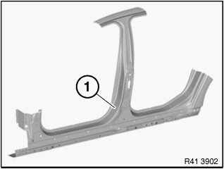
Fig. 134: Identifying B-Pillar
Removing entrance cover with door post
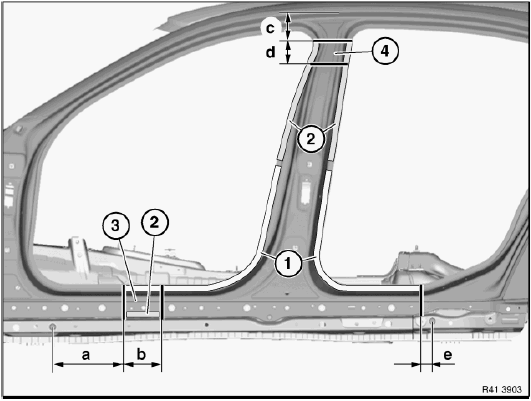
Fig. 135: Removing Entrance Cover With Door Post
Mark severance cuts in accordance with specified dimensions and cut.
IMPORTANT: Cut outer panel only for following severance cuts.
Measurement a = approx. 270 mm from center point of 25 mm dia. hole.
Dimension b = approx. 140 mm after cut a.
Measurement c = approx. 100 mm from roof edge.
Measurement d = approx. 80 mm below cut c.
Measurement e = approx. 40 mm from center point of 25 mm dia. hole.
OPEN spot-welded adhesive joints in areas (1). Open welded connections in areas (2).
Mark severance cut in accordance with specified dimension and cut.
IMPORTANT: Cut outer metal plate only for following severance cut.
Measurement a = approx. 340 mm from center point of 25 mm dia. hole.
Open welded connections in area (1).
Installation note: Apply repair welding spots in area (1) to existing welding spots on new part / vehicle.
This is necessary because the adhesive between the spot flanges acts as an insulator.
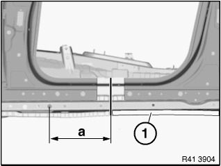
Fig. 136: Identifying Area For Repair Welding (1 Of 2)
Open welded connections in areas (1).
Perform severance cut (2) according to illustration.
Tilt metal section (3) forwards to gain access to the 4 weld joints underneath.
Open the 4 weld joints.
Installation note: Apply repair welding spots in area (1) to existing welding spots on new part / vehicle.
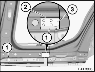
Fig. 137: Identifying Area For Repair Welding (2 Of 2)
IMPORTANT: Open spot-welded adhesive joints in area (1) Open welding spots from outside.
Do not damage inside panel!
Open bonded connection in area (2).

Fig. 138: Identifying Spot-Welded And Bonded Areas
Mark severance cut in accordance with specified dimension and cut.
IMPORTANT: Cut outer metal plate only for following severance cut.
Dimension a =140 mm from the edge of roof frame.
Open weld joint (1).
Remove cover for side member with B-pillar.
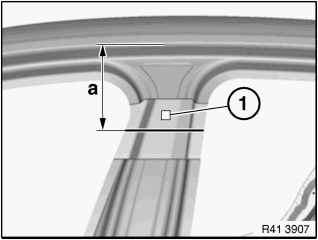
Fig. 139: Identifying Welding Area At Joint
New part preparation
Mark severance cuts on B-pillar in accordance with severance cuts on the vehicle and cut.
IMPORTANT: Do not cut through support (3) for B-pillar reinforcement.
- B-pillar reinforcement outer skin
- B-pillar outer skin
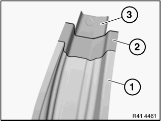
Fig. 140: Identifying Outer Skins And Support For B-Pillar Reinforcement
Mark severance cut (1) and other severance cuts according to the severance cuts on the vehicle and cut.
Partially release metal section (2) as described in removal and tilt forwards.
Open weld joints in area (3) and remove cover for side member (4).
Prepare REINFORCEMENT PLATES at severance cuts.
NOTE: After welding in new part, tilt metal section (2) closed again and weld up.
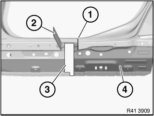
Fig. 141: Welding In New Part
Set 3 6.8 mm Ø bore holes for blind rivets in area (1). Drill from passenger compartment.
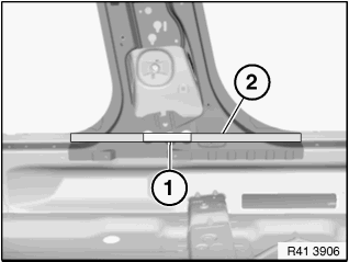
Fig. 142: Identifying Area For Blind Rivets
IMPORTANT: Structure bonding! Observe preparation of bonding surfaces (1).
Adjust new part to fit with set of attachments or universal mount.
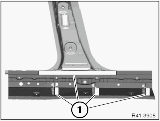
Fig. 143: Identifying Bonding Surfaces
Installing entrance cover with door post
Clean bonding surfaces with cleaning agent R1.
Apply adhesive K1 to bonding surfaces.
Install new parts and reinforcement plates with alignment bracket or universal mount and weld.
Set 3 blind rivets N1.
READ NEXT:
 Replacing Outer Section Of Left Or Right Rear Wheel Housing (Side
Panel Removed)
Replacing Outer Section Of Left Or Right Rear Wheel Housing (Side
Panel Removed)
Read contents of BODY, GENERAL.
Spot-weld bonding is used on this vehicle. Observe specific procedure See
SPOT-WELD BONDING
STEEL PARTS.
Remove or cover those vehicle components in the repair area w
Replacing The Carrier Support Before The Wheel Arch On The Left
Follow procedure for REPAIR STAGE 3.
Read contents of BODY, GENERAL.
Remove or cover those vehicle components in the repair area which are
susceptible to heat or dust.
Use only APPROVED SPOT-WELDI
SEE MORE:
Oil Supply
CHECKING ENGINE OIL PRESSURE
Notes
WARNING: Risk of scalding!
NOTE: To check the engine oil pressure, remove the oil pressure switch and
install and
connect the special tool.
NOTE: A small amount of engine oil emerges when the oil pressure switch is
removed.
Have a cleaning cloth ready.
Necessary
Front Axle - Special Tools
ADAPTER
Adapter MW
Note: (Adapter) For pulling off the taper roller bearings from the
equalization housing in the front axle
differential
Fig. 1: Identifying Adapter (315090)
BUSH
Bush MW
Note: (impact bush) For fitting the radial sealing ring to the drive flange
of the front axle differential
St
