BMW 7 Series: Replacing Engine Support/Front Left Side Frame Connection (Front Left Wheel Arch Removed)
Observe procedure for REPAIR STAGE 3.
Read contents of BODY, GENERAL.
To remove engine support side frame connection
Following new body parts are required:
- Connection, wheel arch/entrance
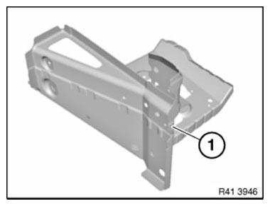
Fig. 121: Identifying Connection, Wheel Arch/Entrance
Open welded connections in areas (1).
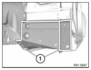
Fig. 122: Identifying Welded Connections Areas
View from below:
Open welded connections in areas (1).
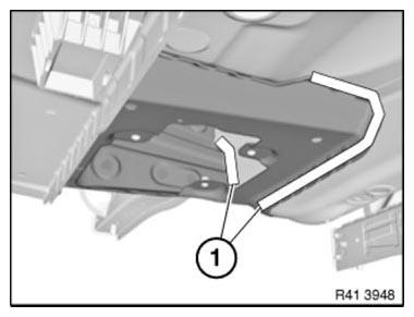
Fig. 123: Identifying Welded Connections Areas
View from below:
Open welded connections in areas (1).
Remove wheel arch/entrance connection.
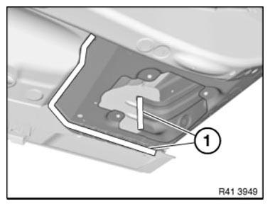
Fig. 124: Identifying Welded Connections Areas
New part preparation
Open welded connections in area (1).
Remove metal section (2).
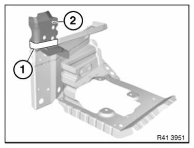
Fig. 125: Identifying Welded Connections Area And Metal Section
To install engine support side frame connection
Install and weld new parts.
READ NEXT:
 Replacing Front Section Of Left Engine Support
Observe procedure of REPAIR STAGE 3.
Read contents of BODY, GENERAL.
Steel-aluminium composite construction is used on the vehicle.
Observe specific procedure.
Use only approved SPOT-WELDING APPAR
Replacing Entrance With Door Post, Left And Right (Partial
Replacement, B-pillar)
Observe procedure of REPAIR STAGE 3.
Read CONTENTS OF BODY, GENERAL.
Spot-weld bonding is used on this vehicle. Observe specific PROCEDURE.
Use only approved spot-welding apparatus for repairs.
Pl
Replacing Outer Section Of Left Or Right Rear Wheel Housing (Side
Panel Removed)
Read contents of BODY, GENERAL.
Spot-weld bonding is used on this vehicle. Observe specific procedure See
SPOT-WELD BONDING
STEEL PARTS.
Remove or cover those vehicle components in the repair area w
SEE MORE:
GPS Receiver Module
The GPS receiver module is also known as the HIP module (Host Independence
Positioning).
Location and route of the vehicle are calculated in the navigation system with
the data from the GPS receiver
module.
This module was already integrated in the head unit with the CCC system. It has
the task
Vertical Dynamics Control (VDC)
Control Unit
Fig. 124: Identifying VDM
INDEX REFERENCE CHART
VDM
The location of the VDM control unit is dependent on the country in which the
vehicle is sold.
On left-hand drive vehicles the control unit is fitted inside the
passenger compartment near the right A-pillar
(as illustrated)
