BMW 7 Series: Removing And Installing/Replacing Central Information Display (CID)
IMPORTANT: Read and comply with NOTES on protection against electrostatic damage (ESD protection).
Necessary preliminary work
F01, 02, 03, 04:
- Remove DECORATIVE STRIP ON DASHBOARD IN MIDDLE
F07, 10, 11, 18:
- Remove decorative strip on dashboard on right
Release screws (1).
Tightening torque 65 50 1AZ.
Guide out CID (2) in direction of arrow.
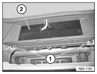
Fig. 77: Identifying Screws And CID
Unlock plug connections (1) and (2) and disconnect.
Remove CID (3).
Installation note: Ensure correct cable routing.
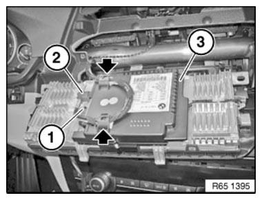
Fig. 78: Identifying Plug Connections And CID
Installation note: Brackets (1) on CID (2) must be seated correctly in intended dashboard guides.
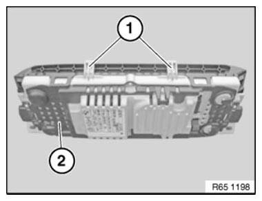
Fig. 79: Identifying Brackets And CID
Replacement
Carry out VEHICLE PROGRAMMING/ENCODING.
REMOVING AND INSTALLING/REPLACING TV MODULE
IMPORTANT: Read and comply with notes on PROTECTION AGAINST ELECTROSTATIC DISCHARGE (ESD PROTECTION).
NOTE: Follow instructions for NOTES ON HANDLING OPTICAL FIBRES.
Necessary preliminary tasks
- Clamp off BATTERY NEGATIVE LEAD
- Remove LEFT LUGGAGE COMPARTMENT WHEEL ARCH TRIM
Release screws (1).
Remove TV module (2).
Unlock and detach plug connections (3 and 4).
Installation: Make sure plug connections (4) are in correct color sequence.
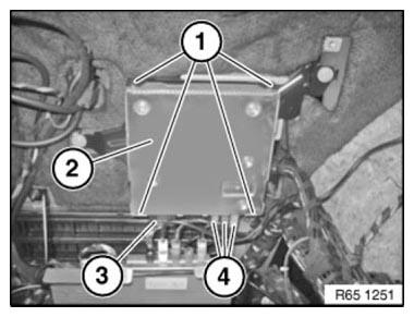
Fig. 80: Identifying Screws, TV Module And Plug Connections
REMOVING AND INSTALLING/REPLACING COVER FOR CENTRAL INFORMATION DISPLAY (CID, JC)
Notes
NOTE: These repair instructions apply to the Central Information Display (CID) of the manufacturer Johnson Controls (JC).
IMPORTANT: Read and comply with notes on PROTECTION AGAINST ELECTROSTATIC DAMAGE (ESD PROTECTION).
Necessary preliminary work
- Remove CENTRAL INFORMATION DISPLAY
Release screws (1).
Tightening torque 65 50 2AZ
NOTE: To tighten screws, use special tool 00 9 460.
Remove rear cover (2) from.
Central Information Display (3).
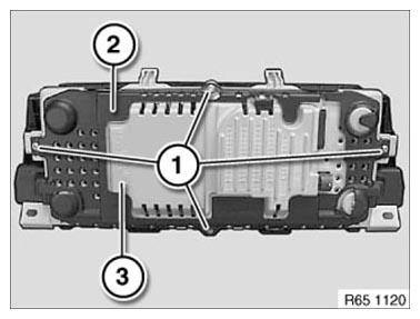
Fig. 81: Identifying Screws, Rear Cover And Central Information Display
Installation note:
Make sure rear cover (2) is correctly seated on Central Information Display (3).
IMPORTANT: Do not damage or scratch the display!
Carefully disconnect the plug connection (1) (only F01, F02, F03, F04 ).
Carefully raise latch mechanisms (2) and remove Central Information Display (3) from Central Information Display cover (4).
Installation note: Make sure latch mechanisms (2) are heard to click into place.
Make sure rear Central Information Display cover (4) is correctly seated on Central Information Display (3).
Ensure correct cable routing in guide (5).
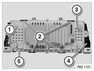
Fig. 82: Identifying Plug Connection, Latch Mechanisms, Central Information
Display Cover And Guide
IMPORTANT: Before/after assembly, cover is bolted to the Central Information Display, correct installation position must first be checked!
Installation note: Before connecting the screw connection, check whether latch mechanisms marked with an arrow are correctly seated.
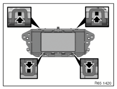
Fig. 83: Identifying Central Information Display Installation Position
Installation note: Before connecting the screw connection, check all-round rim at the places marked with an arrow.
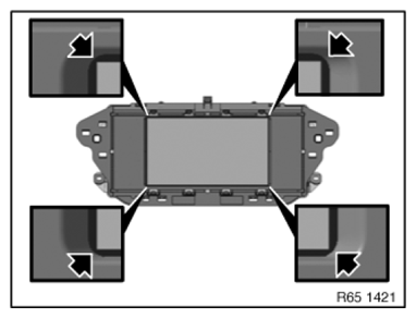
Fig. 84: Identifying Screw Connection Installation Position
READ NEXT:
 Removing And Installing/Replacing Cover For Rear Passenger
Compartment Monitor At Front
Removing And Installing/Replacing Cover For Rear Passenger
Compartment Monitor At Front
IMPORTANT: Read and comply with NOTES on protection against electrostatic
damage (ESD protection).
Necessary preliminary work
Remove COVER FOR REAR PASSENGER COMPARTMENT MONITOR AT REAR
IMPORTANT:
Anti-Theft Alarm System
REMOVING AND INSTALLING/REPLACING EMERGENCY POWER SIREN WITH
TILT SENSOR
Necessary preliminary work
Remove GUIDE FOR BUMPER AT REAR RIGHT
Secure guide for bumper (3) against falling out.
Unfasten
Pedestrian Protection
REMOVING AND INSTALLING (REPLACING) LEFT PEDESTRIAN PROTECTION
SENSOR
WARNING: Observe SAFETY INSTRUCTIONS for handling gas generators.
Incorrect handling can activate pedestrian protection and cause
SEE MORE:
Introduction
The Steering Column Switch Cluster - An Interface
The steering column switch cluster is a "mechanical and electrical interface"
from the steering wheel to the
vehicle; it is firmly connected mechanically to the steering column. On top of
this purely mechanical
connection, the steering column switc
Water Pump With Drive
Removing And Installing/Renewing Coolant Pump (N63)
WARNING: Risk of scalding!
Only perform this work after engine has cooled down.
Recycling
Catch and dispose of drained coolant in a suitable collecting vessel.
Observe country-specific waste disposal regulations.
IMPORTANT: If a coolant pump which
