BMW 7 Series: Removing And Installing/Replacing Cover For Rear Passenger Compartment Monitor At Front
IMPORTANT: Read and comply with NOTES on protection against electrostatic damage (ESD protection).
Necessary preliminary work
- Remove COVER FOR REAR PASSENGER COMPARTMENT MONITOR AT REAR
IMPORTANT: Do not damage or scratch display.
Release screws (1).
Tightening torque 65 50 1AZ.
Carefully disconnect plug connection (3).
Remove rear passenger compartment monitor (4) from cover (5).
Installation note: Ensure correct cable routing in guides (2).
Make sure cover (5) is correctly seated on rear passenger compartment monitor (4).
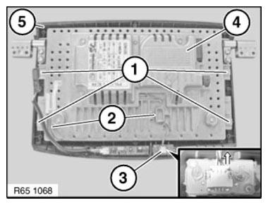
Fig. 85: Identifying Screws, Plug Connection, Rear Passenger Compartment
Monitor, Guides And Cover
REMOVING AND INSTALLING/REPLACING FRICTION HINGES FOR REAR CABIN MONITOR
IMPORTANT: Read and comply with notes on PROTECTION AGAINST ELECTROSTATIC DAMAGE (ESD PROTECTION)
Do not damage or scratch display.
Necessary preliminary tasks
- Remove REAR CABIN MONITOR
Release screws (1).
Tightening torque 65 50 1AZ.
Remove cover (3) from rear cabin monitor (4), unclipping plug (2) and feed out cable.
Installation: Make sure cover (3) is correctly seated on rear cabin monitor (4).

Fig. 86: Identifying Cover, Rear Cabin Monitor, Unclipping Plug And Screws
Unfasten screws (2).
Tightening torque 65 50 2AZ.
Remove friction hinges (1) from rear cabin monitor (3).
Installation
Observe gap dimension adjustment when screwing friction hinges (2) to rear cabin monitor (3) on left and right.
Gap dimensions:
- 0.9 mm
- 1.5 mm
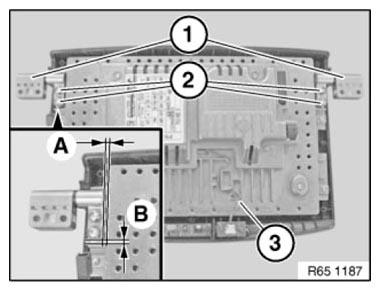
Fig. 87: Identifying Screws, Friction Hinges And Rear Cabin Monitor
REMOVING AND INSTALLING/REPLACING LEFT OR RIGHT REAR MONITOR
IMPORTANT: Read and comply with notes on protection against electrostatic damage (ESD PROTECTION).
Installation note:
- Remove REAR PASSENGER COMPARTMENT MONITOR COVER
Release screws (1).
Remove rear passenger compartment monitor (2) from holder (3).
Installation note: Make sure rear passenger compartment monitor (2) is correctly seated on holder (3).
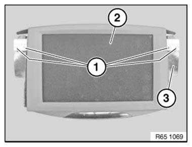
Fig. 88: Identifying Screws, Rear Passenger Compartment Monitor And Holder
Unlock plug connections and disconnect.
Remove monitor in rear (1).
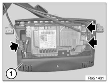
Fig. 89: Removing Plug Connections And Monitor
REMOVING AND INSTALLING/REPLACING TRIM FOR REAR MONITOR DISPLAY AT REAR
IMPORTANT: Read and comply with NOTES on protection against electrostatic damage (ESD protection).
Necessary preliminary work
- REMOVE REAR MONITOR
Release screws (1).
Tightening torque 65 50 1AZ.
Remove cover (3) from rear monitor (4), unclipping plug (2) and feed out cable.
Installation note: Make sure cover (3) is correctly seated on rear monitor (4).
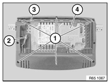
Fig. 90: Identifying Screws, Cover, Rear Monitor And Unclip Plug
REMOVING AND INSTALLING/REPLACING VIDEO SWITCH
IMPORTANT: Read and comply with notes on PROTECTION AGAINST ELECTROSTATIC DISCHARGE (ESD PROTECTION).
NOTE: Follow instructions for NOTES ON HANDLING OPTICAL FIBRES.
Necessary preliminary tasks
- Disconnect BATTERY NEGATIVE LEAD
- Remove LUGGAGE COMPARTMENT WHEEL ARCH TRIM on left.
NOTE: Video switch is located on the back of the bracket for the TV module.
Release screws (1) and nuts (2).
Remove TV module (3) including bracket.
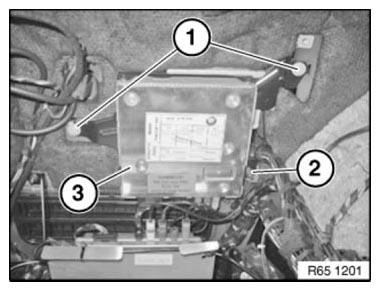
Fig. 91: Identifying Screws, Nuts And TV Module
Release screws (1).
Unfasten plug connection (2) and disconnect.
Remove video switch (3).
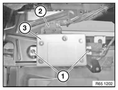
Fig. 92: Identifying Screws, Plug Connection And Video Switch
READ NEXT:
 Anti-Theft Alarm System
REMOVING AND INSTALLING/REPLACING EMERGENCY POWER SIREN WITH
TILT SENSOR
Necessary preliminary work
Remove GUIDE FOR BUMPER AT REAR RIGHT
Secure guide for bumper (3) against falling out.
Unfasten
Pedestrian Protection
REMOVING AND INSTALLING (REPLACING) LEFT PEDESTRIAN PROTECTION
SENSOR
WARNING: Observe SAFETY INSTRUCTIONS for handling gas generators.
Incorrect handling can activate pedestrian protection and cause
SEE MORE:
Risk Of Injury If Oil Comes Into Contact With Eyes And Skin
Danger of injury!
Contact with eyes or skin may result in injury!
Possible symptoms are:
Impaired sight
Irritation of the eyes
Reddening of the skin
Rough and cracked skin
Protective measures/rules of conduct
Wear safety goggles
Wear oil-resistant protective gloves
Observe country-specific
Electronic Ride-Height Control (EHC)
Control Unit
The EHC control unit is located in a module carrier in the rear of the
luggage compartment on the right-hand
side.
Fig. 132: Identifying Air Supply (LVA) And EHC Control Module On Mounting
Bracket
INDEX REFERENCE CHART
Air supply (LVA)
EHC control module on mounting bracket
The E
