BMW 7 Series: Removing And Installing Door
IMPORTANT: Do not damage adjoining body parts.
The illustrations are schematic representations and are to be applied to the relevant vehicle type.
Open door.
Release screw on connector frame.
Front door: Tightening torque 41 51 4AZ.
Rear door: Tightening torque 41 52 4AZ.
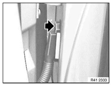
Fig. 402: Locating Screw On Connector Frame
NOTE: Secure door against closing.
Release screw (1) on door retainer.
Front door: Tightening torque 51 21 3AZ.
Rear door: Tightening torque 51 22 3AZ.
Open door up to stop.
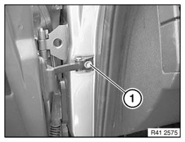
Fig. 403: Identifying Screw On Door Retainer
Release screws between both hinge elements at top and bottom.
Front door: Tightening torque 41 51 1AZ.
Rear door: Tightening torque 41 52 1AZ.
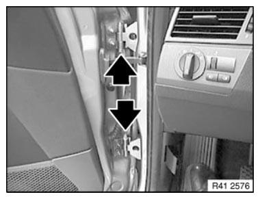
Fig. 404: Locating Hinge Elements
Pull plug connection from door pillar, unlock by pulling out bar and detach.
Unhinge door by moving upwards and placing it on a suitable surface.
Installation: If necessary, adjust DOOR.
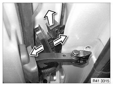
Fig. 405: Pulling Plug Connection From Door Pillar
READ NEXT:
 AFGS (Active Pedestrian Protection) Procedure After Accident
The AFGS system consists of the following components:
Satellites (control unit + sensor)
Sensors, inside, bumper trim, left/middle/right
ACSM control unit (Crash Safety Module)
Cables and c
Adjusting Engine Compartment Lid
IMPORTANT: The BATTERY NEGATIVE LEAD must be clamped off on vehicles with
AFGS
active pedestrian protection!
Do not damage adjoining body components!
Minor corrections (realignment work) are permitte
SEE MORE:
Blind spot collision warning- Warning function
Light in the exterior mirror
Prewarning
The dimmed light in the exterior mirror indicates
when there are vehicles in the blind spot or approaching
from behind.
Acute warning
When the turn signal is switched on while a vehicle
is in the critical zone, the steering wheel vibrates
briefly and the lig
Removing And Installing/Replacing Left Turn Indicator Insert
Necessary preliminary tasks
Remove LEFT HEADLIGHT
Release screws (1) on headlight.
Tightening torque 63 12 6AZ.
Remove turn indicator insert (2) from headlight (3) towards top.
Fig. 72: Identifying Headlight Screws
Disconnect plug connection (1) on turn indicator insert (2).
Fig. 73: Identify
