BMW 7 Series: Reinforcement Plate With Stud Bolt (Bonded)
In the case of a partial replacement piece, a body component is cut at a point described in the repair instructions.
A reinforcement plate is bonded in to ensure sufficient strength.
Reinforcement plates are available as new parts and must also be used (refer to Electronic Parts Catalogue).
NOTE: The following graphics serve as general illustrations of reinforcement plate repair work. They are applicable to sectional repairs in the outer skin area.
Overview of reinforcement plates:
- Reinforcement plate, sill
- Reinforcement plate, C-pillar
- Reinforcement plate, universal
- Reinforcement plate, C- or D-pillar
- Lock nuts (not pictured)
- Plastic nut 18 mm, part number 1 943 122
- Clip nut 30 mm, part number 7 139 081
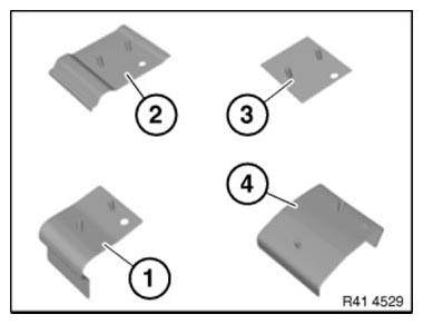
Fig. 361: Identifying Reinforcement Plate Sill, C-Pillar, Universal And C- Or
D-Pillar
Mark component in accordance with dimension a and cut.
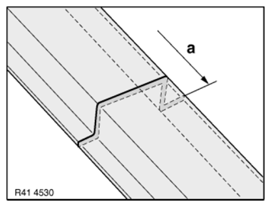
Fig. 362: Identifying Component Cutting Dimension
Preparation of new part
The reinforcement plates must if necessary be reworked and cut to size.
Adjust reinforcement plate (1) to fit in component (2) on vehicle.
Make recesses (3) for stud bolts (4) in a semicircular shape.
Diameter of recesses approx. 10 - 12 mm.
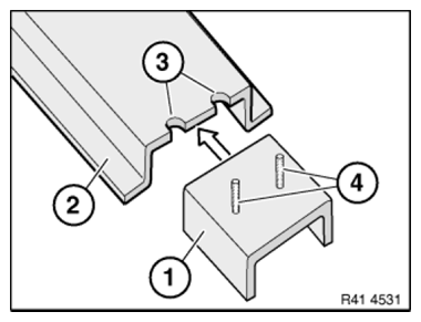
Fig. 363: Adjusting Reinforcement Plate
Secure reinforcement plate by screwing on lock nuts (1).
Fit new part (2). Make recesses (3) in new part in a semicircular shape.
Diameter of recesses approx. 10 - 12 mm.
Remove reinforcement plate again.
NOTE: Width of joint between new part and component on vehicle approx. 3 - 8 mm (at least 30 mm flange width per side).
Plastic nuts should be screwed on once before applying adhesive (no thread in new plastic nut)!
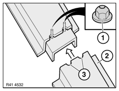
Fig. 364: Fitting New Part
Round off cutting edges (1) on joint by grinding.
(2) Component on vehicle
(3) New part
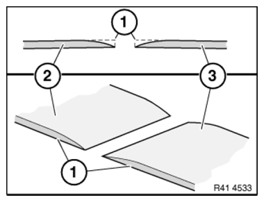
Fig. 365: Identifying Cutting Edges
IMPORTANT: Do not grind new part and body in area of bonding surfaces.
Procedure for using universal reinforcement plate
The universal reinforcement plate needs to be adapted. The plate must be divided if the distance between the pins is too great.
Dimension a is between 40 and 80 mm depending on the space available.
Secure plates with N4 punch rivets.
NOTE: Ensure the rivet is positioned correctly! Rivet head is on the adhesion side! Rivet the plate to the inside of the flange!
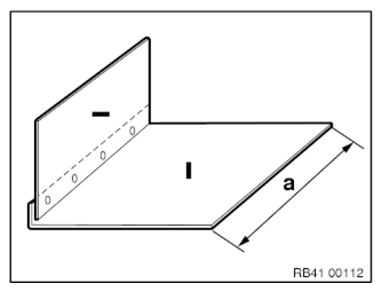
Fig. 366: Identifying Universal Reinforcement Plate Dimension
Installing reinforcement plate
Clean all bonding surfaces.
Apply adhesive to reinforcement plate in area (1).
Apply more adhesive in the radii to avoid air pockets.
Carefully slide reinforcement plate into component on vehicle and secure by screwing on nuts (2).
Screw on nuts a few turns only.
IMPORTANT: When joining reinforcement plate, make sure there is sufficient adhesive on bonding surfaces.
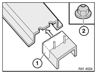
Fig. 367: Identifying Reinforcement Plate Adhesive Applying Area
Apply adhesive to reinforcement plate bonding surface (1). Apply more adhesive in the radii to avoid air pockets.
Fit new part (2).
Align new part to adjoining component and secure with gripping pliers.
Tighten nuts.
Tightening torque 41 14 1AZ.
IMPORTANT: Check that the transition of the components is OK at the separation point.
Corrections can only be made before the adhesive has hardened. Straightening at a later stage is not possible.
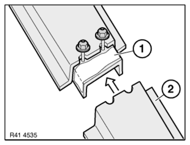
Fig. 368: Fitting New Part
Concluding tasks at separation point:
After adhesive has hardened:
In area visible to customer:
Cut off stud bolts with bodywork saw.
Completely remove adhesive residue in joint (1).
Round off sharp edges by grinding.
IMPORTANT: Avoid heating the separation point by excessive grinding.
Reworking by pressing not permitted!
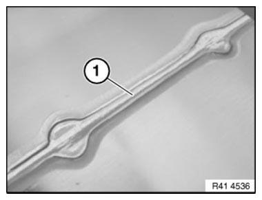
Fig. 369: Identifying Reinforcement Plate Joint
Only the BMW-approved METAL FILLER should be used on the joint.
METAL FILLER - INSTRUCTIONS FOR USE
Not in area visible to customer: Examples: The joint is covered by sill trim panel, windows, seals, etc.
Grind off stud bolts and surplus adhesive flush. Do not use metal filler. Paint area as specified in BMW Painting Handbook.
NOTE: After painting, the joint becomes visible as the adhesive shrinks. This has no affect on the quality.
Removing And Installing Front Side Wall On Left
Observe GAP DIMENSIONS.
IMPORTANT: Do not damage adjoining body components.
Necessary preliminary work
- Remove SIDE REPEATER
- Remove wheel arch covers
- Remove TRIM PANEL FOR COVER ON SIDE MEMBER
- Partially loosen BUMPER TRIM on the side
- Remove SEAL MOUNTING for engine compartment lid
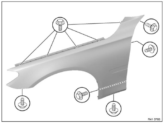
Fig. 370: Identifying Trim Panel Screws
Release screws.
Tightening torque 41 35 1AZ.
Tightening torque 41 35 2AZ.
Replacement
Apply additional sealant to inside of front panel in area (1). Apply to area (1) based on shape of side wall to be replaced.
Material: SEALANT D1 (sourcing reference via BMW Parts Department).
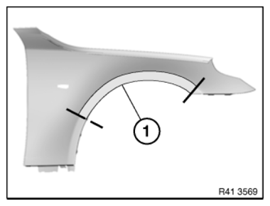
Fig. 371: Identifying Front Panel Sealant Applying Area
READ NEXT:
 Replacing Left Rear Side Wall
Read contents of BODY, GENERAL.
STRIP DOWN VEHICLE
Observe new procedure for bonding and riveting (REPAIR STAGE 2).
Following new body parts are required:
Side frame, rear
Reinforcement plate, C-
Replacing Outer Section Of Left Or Right Rear Wheel Housing (Side
Panel Removed)
Read contents of BODY, GENERAL.
Spot-weld bonding is used on this vehicle. Observe specific procedure See
SPOT-WELD BONDING
STEEL PARTS.
Remove or cover those vehicle components in the repair area
SEE MORE:
Drive, Roller Sun Blind/Sun Visor
REMOVING AND INSTALLING OR REPLACING DRIVE UNIT FOR ROLLER SUN
BLIND
Necessary preliminary tasks
Remove REAR WINDOW ROLLER BLIND
Release screws (1).
Remove drive linkage (2).
Installation:
Drive linkage (2) can only be installed in one position.
Fig. 63: Identifying Drive Linkage With Mounting
Electronic Power Steering
ADJUSTMENT/INITIAL OPERATION FOR ACTIVE FRONT STEERING
NOTE: Adjustment/start-up of the active steering must be carried out:
Before adjustment work on the front axle/steering
After work on the steering column
After replacement of following components:
Active front steering control unit
ICM c
