BMW 7 Series: Replacing Left Rear Side Wall
Read contents of BODY, GENERAL.
STRIP DOWN VEHICLE
Observe new procedure for bonding and riveting (REPAIR STAGE 2).
Following new body parts are required:
- Side frame, rear
- Reinforcement plate, C-pillar (not shown)
- Reinforcement plates (not pictured)
- Lock nuts (not pictured)
Following consumables are required:
MATERIAL CHART
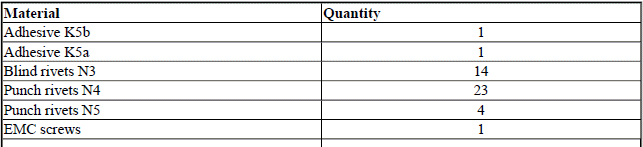
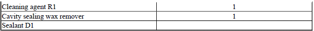
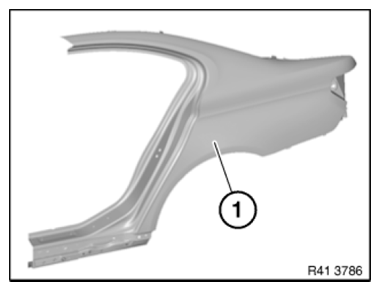
Fig. 372: Identifying Side Frame, Rear
Removing side wall
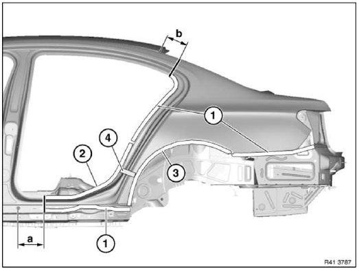
Fig. 373: Identifying Cavity Sealing, Welded Connections Areas And
Spot-Welded Adhesive Joints Area
Mark severance cuts in accordance with specified dimensions and cut.
IMPORTANT: Cut outer panel only.
Compare position of severance cuts with REINFORCEMENT PLATES.
Dimension a = approx. 200 mm from center point of 25 mm dia. hole.
Dimension b = approx. 115 mm from roof edge.
Open welded connections in areas (1).
Open spot-welded adhesive joints in area (2) Open FOLDED BONDED CONNECTION in area (3).
Loosen side wall of cavity sealing (4).
NOTE: In addition to the dimensions, a TEMPLATE (1) may be used to determine the position of the separating cut.
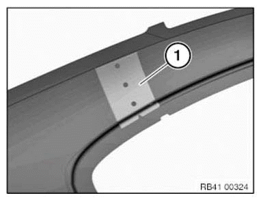
Fig. 374: Identifying Template
Open welded connections in areas (1) and (2).
IMPORTANT: In areas (2), the welding spots must be released from the side wall.
Take off side wall.
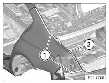
Fig. 375: Identifying Welded Connections Areas
Open welded connections in area (1).
Release bonded joint (2).
Remove lock striker reinforcement.
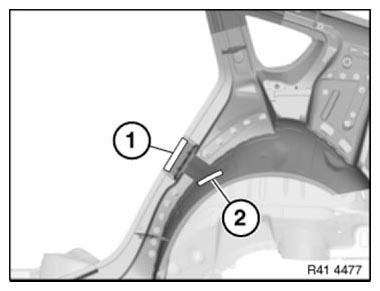
Fig. 376: Identifying Welded Connections Areas And Bonded Joint
Preparation of new part
Mark severance cuts on the new part according to vehicle and cut.
Prepare REINFORCEMENT PLATES (bonded) at all severance cuts.
Separate weld joints in area (1) from inside.
Remove sill section (2).
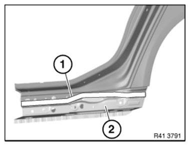
Fig. 377: Identifying Weld Joints Area And Sill Section
Adjust new part to fit and secure.
In areas (1) and (2) set 4.2 mm dia. holes for blind rivets:
Area (1): 5 bore holes
Area (2): 4 bore holes
F02 only:
In area (1) 6 holes
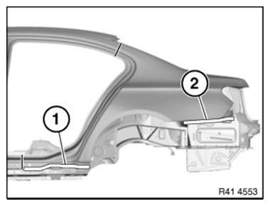
Fig. 378: Identifying Blind Rivets Holes Areas
In areas (1) and (2) set 4.2 mm dia. holes for blind rivets:
Area (1): 3 bore holes
Area (2): 1 bore holes
Remove new part again and deburr bore holes.
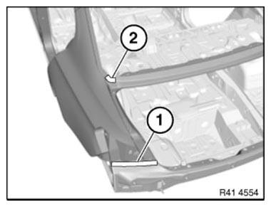
Fig. 379: Identifying Blind Rivets Holes Area
IMPORTANT: Do not grind/sand new part in area of bonding surfaces.
Installing side wall
Clean all bonding surfaces on vehicle, on the new part and on the reinforcement plates with cleaning agent R1.
Apply adhesive to reinforcement plates. Install reinforcement plates.
Apply adhesive in areas (1).
Apply sealing compound to CAVITY SEALING at area 2.
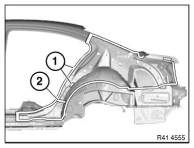
Fig. 380: Identifying Adhesive Applying Areas
Apply adhesive in area (1) of lock striker reinforcement.
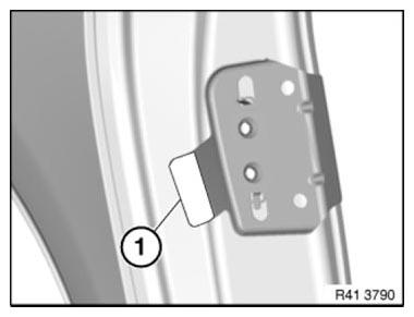
Fig. 381: Identifying Lock Striker Reinforcement Adhesive Applying Area
Apply adhesive (1) to inside of side wall at distance a.
Dimension a = approx. 5 mm.
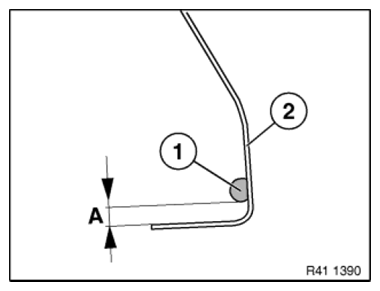
Fig. 382: Identifying Side Wall Adhesive Applying Area
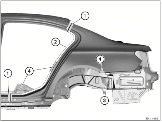
Fig. 383: Identifying Reinforcement Plates And Punch Rivets Area
Install side wall with a second person helping.
NOTE: When installing side wall, make sure there is sufficient adhesive on bonding surfaces.
After adjusting side wall to fit, tighten nuts of reinforcement plates (1).
Secure side wall in area of reinforcement plates with gripping pliers.
Rivet side wall with blind rivets N3.
Use 11 punch rivets N4 in area (2).
Use 2 punch rivets N4 in area (3).
In areas (4), fix the side wall using gripping pliers until the adhesive hardens.
Use N4 punch rivets in areas (1) to (3).
Use punch rivets N5 in areas (4) and (5).
IMPORTANT: In area (4), the punch rivets must be set from the side wall.
PUNCH RIVETS AREAS CHART

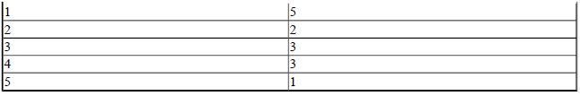
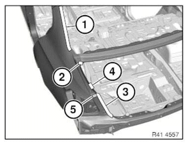
Fig. 384: Identifying Punch Rivets Area
Also apply adhesive (2) to outer wheel arch section (3).
- Rear side wall.
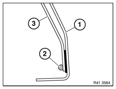
Fig. 385: Identifying Outer Wheel Arch Section Adhesive Applying Area
Flange edge of wheel arch (3) of side wall flush to outer wheel arch section.
Do not create sharp edges when flanging as otherwise the flange edge may begin to tear.
Dimension (A) = 5 mm.
- Adhesive
- Rear side wall
Also seal in area (3) according to standard.
IMPORTANT: Flange edge must be completely filled with adhesive!
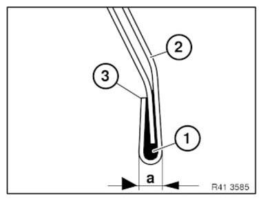
Fig. 386: Identifying Rear Side Wall Adhesive Applying Area
After adhesive has hardened in sill area, install an EMC SCREW.
READ NEXT:
 Replacing Outer Section Of Left Or Right Rear Wheel Housing (Side
Panel Removed)
Replacing Outer Section Of Left Or Right Rear Wheel Housing (Side
Panel Removed)
Read contents of BODY, GENERAL.
Spot-weld bonding is used on this vehicle. Observe specific procedure See
SPOT-WELD BONDING
STEEL PARTS.
Remove or cover those vehicle components in the repair area
Adjust Door
IMPORTANT: Do not damage adjoining body components.
Minor corrections (realignment work) are permitted if the existing adjustment
options are not sufficient.
NOTE: Observe GAP DIMENSIONS.
The door m
SEE MORE:
Functional Areas of Integrated Active Steering
Low Speed Range
The variable steering-gear ratio of the Active Steering component reduces
steering effort to approximately 2
turns of the steering wheel from lock to lock. In the low speed range up to
approximately 37 mph, the variable
steering-gear ratio for the front wheels is combined with a de
Removing And Installing/Replacing A Steering Stub/Wheel Carrier
Remove REAR WHEEL.
IMPORTANT: Expand anti-twist lock sufficiently to avoid damaging thread
when releasing
collar nut.
Release collar nut (1), activate parking brake for this purpose.
Installation note:
Replace collar nut, oil collar nut/wheel bearing contact surface only and
tighten down.
No oil
