BMW 7 Series: Adjust Door
IMPORTANT: Do not damage adjoining body components.
Minor corrections (realignment work) are permitted if the existing adjustment options are not sufficient.
NOTE: Observe GAP DIMENSIONS.
The door must be provided with all add-on parts for correct adjustment.
Adjust screwed body components from rear to front.
The following illustrations are schematic representations and are to be applied to the relevant vehicle type.
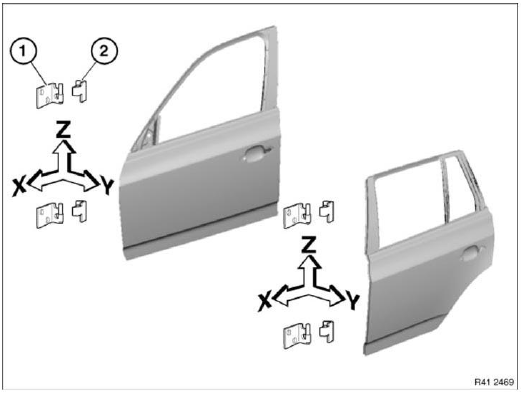
Fig. 390: Adjusting Door
Slacken lock striker, remove if necessary.
Slacken screws for hinge (2) on door until door can still just be moved.
Front door: Tightening torque 41 51 2AZ.
Rear door: Tightening torque 41 52 2AZ.
If adjustment range is not sufficient, slacken screws for hinges (1) on body.
NOTE: Screw connections only accessible from inside.
Front door: Tightening torque 41 51 3AZ.
Rear door: Tightening torque 41 52 3AZ.
Check that adjoining body components are flush in terms of height and correct if necessary.
NOTE: Height adjustment of door must not be influenced by lock striker.
When the door is closed, the lock striker must not touch or scrape against the door lock.
Look out for scratch marks.
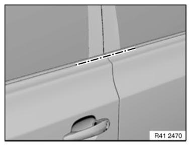
Fig. 391: Identifying Door Mark
Tighten down screws (1) until lock striker can still just be moved.
Move lock striker sideways in order to adjust transition between door and adjoining bodywork parts.
Tightening torque 51 22 2AZ.
NOTE: When the door is closed, the lock striker must not touch or scrape against the door lock.
Look out for scratch marks.
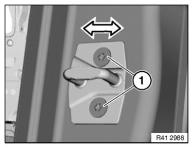
Fig. 392: Moving Lock Striker
After setting
If the hinge is slackened on the body side, the area of the hinge must be sealed in a u-shape with sealant (1).
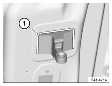
Fig. 393: Identifying Hinge Sealant Applying Area
- Tighten all screws to specified torque.
- Touch up unpainted surfaces in the appropriate color.
- If necessary, adjust front door.
READ NEXT:
 Removing And Installing Door
IMPORTANT: Do not damage adjoining body parts.
The illustrations are schematic representations and are to be applied to the
relevant vehicle type.
Open door.
Release screw on connector frame.
Fron
Adjust Door
IMPORTANT: Do not damage adjoining body components.
Minor corrections (realignment work) are permitted if the existing adjustment
options are not sufficient.
NOTE: Observe GAP DIMENSIONS.
The door m
SEE MORE:
Removing And Installing/Replacing Oil Pump (N63)
Notes
IMPORTANT: All adjusting procedures on the chain drive must be observed.
A timing chain which is tensioned too tautly can cause noises in the chain
drive.
A timing chain that is too slack can cause the timing chain to jump.
Risk of damage in oil pump drive.
Necessary preliminary work
DRAI
Leak Detection With Ultraviolet Additives (UV Additives) (BMW Leak-Testing
Case)
IMPORTANT: The UV leakage detection procedure is not permitted in EU
countries!
Observe national regulations in all other countries!
IMPORTANT: It is absolutely essential to read and comply with the
equipment manufacturer's
operating instructions use provided in the equipment case!
Read and comply
