
BMW 7 Series: Removing And Installing Door
IMPORTANT: Do not damage adjoining body parts.
The illustrations are schematic representations and are to be applied to the relevant vehicle type.
Open door.
Release screw on connector frame.
Front door: Tightening torque 41 51 4AZ.
Rear door: Tightening torque 41 52 4AZ.
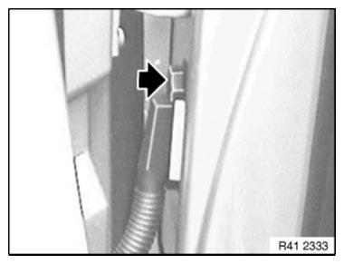
Fig. 394: Locating Screw On Connector Frame
NOTE: Secure door against closing.
Release screw (1) on door retainer.
Front door: Tightening torque 51 21 3AZ.
Rear door:
Tightening torque 51 22 3AZ.
Open door up to stop.
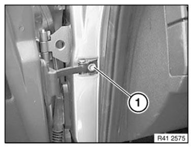
Fig. 395: Identifying Screw On Door Retainer
Release screws between both hinge elements at top and bottom.
Front door: Tightening torque 41 51 1AZ.
Rear door: Tightening torque 41 52 1AZ.
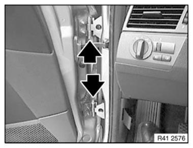
Fig. 396: Locating Hinge Elements
Pull plug connection from door pillar, unlock by pulling out bar and detach.
Unhinge door by moving upwards and placing it on a suitable surface.
Installation: If necessary, adjust DOOR.
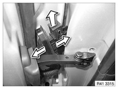
Fig. 397: Pulling Plug Connection From Door Pillar
READ NEXT:
 Adjust Door
IMPORTANT: Do not damage adjoining body components.
Minor corrections (realignment work) are permitted if the existing adjustment
options are not sufficient.
NOTE: Observe GAP DIMENSIONS.
The door m
Removing And Installing Door
IMPORTANT: Do not damage adjoining body parts.
The illustrations are schematic representations and are to be applied to the
relevant vehicle type.
Open door.
Release screw on connector frame.
Fron
SEE MORE:
Turning Lights
The turning light function is available only in connection with the option
Adaptive Headlight. In addition to the
adaptive headlights, the turning light additionally illuminates the area in
front of and beside the vehicle.
The turning light makes it possible to recognize persons or traffic situat
Removing And Installing/Replacing Sensor For Fuel Gauge
Recycling
Fuel escapes when fuel lines are detached. Have a suitable collecting
container ready.
Catch and dispose of escaping fuel.
Observe country-specific waste-disposal regulations.
IMPORTANT: Ensure adequate ventilation in the place of work!
Avoid skin contact (wear gloves)!
Ensure absolute
