BMW 7 Series: Overview Of Aerial Diversity
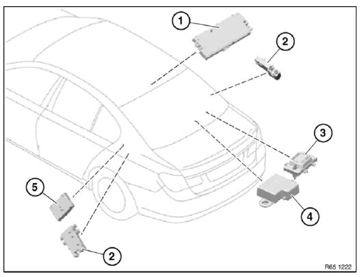
Fig. 101: Overview Of Aerial Diversity
- Aerial amplifier
- Blocking circuit
- AM choke (US vehicles only)
- Back - up aerial
- Interference suppression filter
OVERVIEW OF SENSORS FOR AIRBAG SYSTEM AND PEDESTRIAN PROTECTION
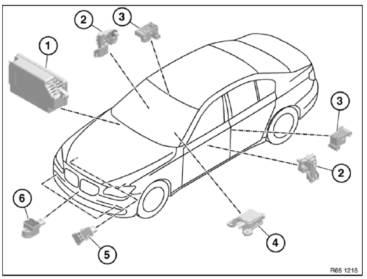
Fig. 102: Overview Of Sensors For Airbag System And Pedestrian Protection
- Airbag control unit (storage tray, passenger side)
- Sensor, front door (left/right)
- Sensor, B-pillar (left/right)
- Central sensor (under centre console)
- Acceleration sensors, front (left/right)
- Sensor, pedestrian protection (middle/left/right)
REMOVING AND INSTALLING (REPLACING) LEFT B-PILLAR SENSOR
WARNING: NOTE AIRBAG SAFETY INSTRUCTIONS ! Incorrect handling can activate airbag and cause injury.
Necessary preliminary tasks
- Clamp off BATTERY NEGATIVE LEAD
- Remove PANEL FOR DOOR PILLAR.
Release screw (1) on B-pillar (3).
Release screw (2).
Installation:
Tightening torque 65 77 3AZ.
Make sure sensor is mounted without play.
Feed out B-pillar sensor in downward direction.
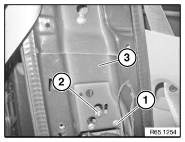
Fig. 103: Identifying Screws And B-Pillar
Unfasten plug connection (1) and disconnect.
Remove B-pillar sensor (2).
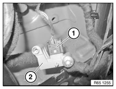
Fig. 104: Identifying Plug Connection And B-Pillar Sensor
REMOVING AND INSTALLING (REPLACING) LEFT FRONT DOOR SENSOR
WARNING: Note AIRBAG SAFETY REGULATIONS ! Incorrect handling can activate airbag and cause injury.
Necessary preliminary tasks
- Remove SOUND INSULATION IN FRONT DOOR
Release screw (1).
Tightening torque 65 77 4AZ.
Feed out sensor towards bottom.
Unlock associated plug connection and disconnect.
Remove sensor.
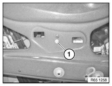
Fig. 105: Identifying Screw
Installation note: Make sure front door sensor (1) is in correct installation position.
Guide lug (2) must be correctly seated in corresponding mounting on front door.
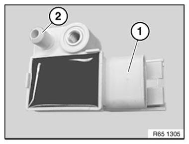
Fig. 106: Identifying Front Door Sensor And Guide Lug
REMOVING AND INSTALLING (REPLACING) LEFT PEDESTRIAN PROTECTION SENSOR
WARNING: Observe SAFETY INSTRUCTIONS for handling gas generators.
Incorrect handling can activate pedestrian protection and cause injury.
Necessary preliminary work
- Disconnect BATTERY CABLE
- Remove ORNAMENTAL GRILLE IN BUMPER TRIM.
Release screws (1).
Tightening torque 65 76 1AZ.
Feed out sensor (2).
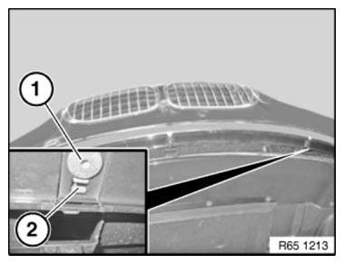
Fig. 107: Identifying Screws And Sensor
Unfasten plug connection (1) and disconnect.
Remove sensor (2).
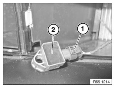
Fig. 108: Identifying Plug Connection And Sensor
REMOVING AND INSTALLING/RENEWING RIGHT FRONT DOOR SENSOR
This operation is described in: REMOVING AND INSTALLING (REPLACING) LEFT FRONT DOOR SENSOR
READ NEXT:
 Removing And Installing/Replacing Airbag Control Unit
IMPORTANT: Read and comply with NOTES on protection against electrostatic
damage (ESD
protection)!
WARNING: NOTE AIRBAG SAFETY INSTRUCTIONS!
Incorrect handling can activate airbag and cause injury.
N
Removing And Installing/Replacing Middle Pedestrian Protection Sensor
WARNING: Observe SAFETY INSTRUCTIONS for handling gas generators.
Incorrect handling can activate pedestrian protection and cause injury.
Necessary preliminary work
Disconnect BATTERY CABLE
Remove
Car Communication Computer (CCC)
REMOVING AND INSTALLING (REPLACING) CAR INFORMATION COMPUTER (CIC)
IMPORTANT: Risk of damage!
A hard disk is installed in the Car Information Computer (CIC).
Carry out mechanical work on the CIC and
SEE MORE:
Release Transmission Lock Electronically
For various tasks, it is necessary to unlock and lock the parking lock.
Before unlocking the parking lock, secure the vehicle against rolling away.
Emergency release is only possible if the engine does not start and the
starter turns over.
If an emergency release needs to be performed although
Car Communication Computer (CCC)
REMOVING AND INSTALLING (REPLACING) CAR INFORMATION COMPUTER (CIC)
IMPORTANT: Risk of damage!
A hard disk is installed in the Car Information Computer (CIC).
Carry out mechanical work on the CIC and adjacent components with care.
Avoid subjecting the CIC to vibration/shocks.
IMPORTANT: Read and co
