BMW 7 Series: Flushing Transmission Oil Cooler With Lines (Automatic Transmission)
Notes
NOTE: Carry out the work steps listed when: Installing a new or replacement transmission.
Flushing can only be carried out with the automatic transmission removed.
Procedure
Automatic transmission removed.
Connect appropriate adapters (see description below) to oil lines exiting from automatic transmission.
Connect connecting line 17 2 019 from the oil collection unit with the quick-release coupling.
Connect drain line 17 2 018 using quick-release coupling.
Hold and direct open end of drain line into a suitable drip tray.
Using oil collection unit, flush approx. 1 liter of transmission fluid (refer to BMW Service Operating Fluids) through oil lines and transmission oil cooler.
Reposition quick-release couplings.
Flush oil lines/transmission oil cooler in opposite direction with approx. 1 liter of transmission fluid (refer to BMW Service Operating Fluids).
Disconnect quick-release couplings.
Remove adapter.
NOTE: Dispose of flushing oil correctly.
Do not reuse under any circumstances.
Arrangement, flushing apparatus for transmissions A5S 310Z, A5S 560Z, A5S 360R/390R, A4S 200R, A5S 325Z
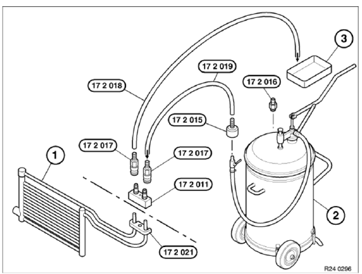
Fig. 60: Arrangement Flushing Apparatus For Transmissions (A5S 310Z, A5S
560Z, A5S 360R/390R,
A4S 200R, A5S 325Z)
- Transmission oil cooler with lines
- Oil collection unit
- Oil drip tray
17 2 011 Adapter for connecting transmission-side oil cooler lines (1)
17 2 015 Connection for oil collection unit (2), manufacturer: Deutsche
Tecalemit or
17 2 016 Connection for oil collection unit (2), manufacturer: Horn
17 2 017 Quick-release coupling (2 pieces)
17 2 018 Hose to oil drip tray (3)
17 2 019 Hose to oil collection unit (2)
17 2 021 Mounting plate for adapter 17 2 011 for transmissions A5S 325Z,
GA6HP26Z
Arrangement of flushing apparatus for transmission A4S 310R
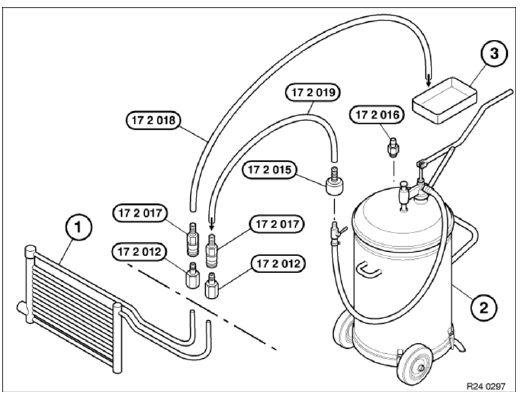
Fig. 61: Arrangement Of Flushing Apparatus For Transmission (A4S 310R)
- Transmission oil cooler with lines
- Oil collection unit
- Oil drip tray
17 2 012 Adapters (2 x) for connecting transmission-side oil cooler lines
(1)
17 2 015 Connection for oil collection unit (2), manufacturer: Deutsche
Tecalemit or
17 2 016 Connection for oil collection unit (2), manufacturer: Horn
17 2 017 Quick-release coupling (2 pieces)
17 2 019 Hose to oil collection unit (2)
Arrangement of flushing apparatus for transmission A4S 300J
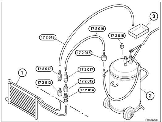
Fig. 62: Arrangement Of Flushing Apparatus For Transmission (A4S 300J)
- Transmission oil cooler with lines
- Oil collection unit
- Oil drip tray
17 2 012 Adapters (2 x) for connecting transmission-side oil cooler lines
(1)
17 2 014 Banjo bolt for connecting transmission-side oil cooler lines (1)
17 2 015 Connection for oil collection unit (2), manufacturer: Deutsche
Tecalemit or
17 2 016 Connection for oil collection unit (2), manufacturer: Horn
17 2 017 Quick-release coupling (2 pieces)
17 2 018 Hose to oil drip tray (3)
17 2 019 Hose to oil collection unit (2)
Arrangement of flushing apparatus for transmission A5S 440Z
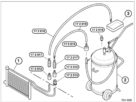
Fig. 63: Arrangement Of Flushing Apparatus For Transmission (A5S 440Z)
- Transmission oil cooler with lines
- Oil collection unit
- Oil drip tray
17 2 012 Adapters (2 x) for connecting transmission-side oil cooler lines
(1)
17 2 013 Banjo bolt for connecting transmission-side oil cooler lines (1)
17 2 015 Connection for oil collection unit (2), manufacturer: Deutsche
Tecalemit or
17 2 016 Connection for oil collection unit (2), manufacturer: Horn
17 2 017 Quick-release coupling (2 pieces)
17 2 018 Hose to oil drip tray (3)
17 2 019 Hose to oil collection unit (2)
FLUSHING TRANSMISSION OIL COOLER WITH LINES (AUTOMATIC
TRANSMISSION) (GA6HP19Z, GAHP26Z, GA6HP32Z)
Notes
NOTE: Carry out the work steps listed when: Installing a new or replacement transmission.
Procedure
Automatic transmission removed.
Connect appropriate adapters (see description below) to oil lines exiting from automatic transmission.
Connect connecting line 17 2 019 from the oil collection unit with the quick-release coupling.
Connect drain line 17 2 018 using quick-release coupling.
Hold and direct open end of drain line into a suitable drip tray.
Using oil collection unit, flush approx. 1 liter of transmission fluid (refer to OPERATING FLUIDS ) through oil lines and transmission oil cooler.
Reposition quick-release couplings.
Flush oil lines/transmission oil cooler in opposite direction with approx. 1 liter of transmission fluid (refer to OPERATING FLUIDS ).
Disconnect quick-release couplings.
Remove adapter.
NOTE: Dispose of flushing oil correctly.
Do not reuse under any circumstances.
Press hydraulic lines (1) into adapters (2).
Slide clamping bar (3) into guides and secure with screw (4).
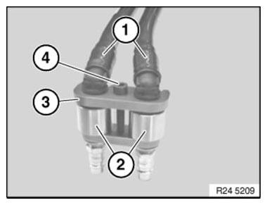
Fig. 64: Identifying Hydraulic Lines, Adapter, Clamping Bars With Screws
Arrangement of flushing apparatus for transmissions GA6HP19Z, GA6HP26Z, GA6HP32Z
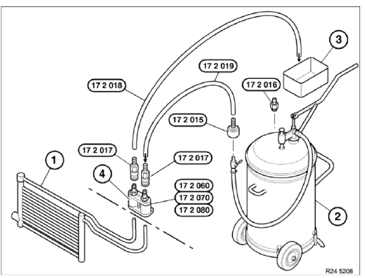
Fig. 65: Arrangement Of Flushing Apparatus For Transmissions (GA6HP19Z,
GA6HP26Z, GA6HP32Z)
- Transmission-oil cooler with lines
- Oil collection unit
17 2 015 Connection for oil collection unit (2), manufacturer: Deutsche
Tecalemit or
17 2 016 Connection for oil collection unit (2), manufacturer: Horn
17 2 017 Quick-release coupling (2 pieces)
17 2 019 Hose to oil collection unit (2)
- Oil drip tray
17 2 018 Hose to oil drip tray (3)
- Adapter with clamping bar
17 2 060 Adapter with clamping bar for aluminium lines and steel lines with
aluminium connection (line
diameter 12 mm) GA6HP19Z
17 2 070 Adapter with clamping bar (line diameter 15 mm) GA6HP26Z, GA6HP32Z, TCT
for N54
engine
17 2 080 Adapter with clamping bar for fuel lines GA6HP26Z
READ NEXT:
 Removing And Installing/Replacing Engine Oil Cooler (N54, N63)
Necessary preliminary tasks
Remove front right WHEEL ARCH TRIM.
WARNING: Danger of scalding!
Only perform this work after engine has cooled down.
IMPORTANT: Wear protective goggles and gloves.
IMPO
Flushing Transmission Oil Cooler With Lines (Automatic
Transmission)
Notes
NOTE: Carry out the work steps listed when:
Installing a new or replacement transmission.
Flushing can only be carried out with the automatic transmission removed.
Procedure
Automatic transmiss
SEE MORE:
Replace The A-Pillar On The Outside Left In The Area Of The
Windscreen
Read contents of BODY, GENERAL.
Remove or cover those vehicle components in the repair area which are
susceptible to heat or dust.
Use only approved SPOT-WELDING APPARATUS for repairs.
IMPORTANT: Operations on pyrotechnical devices may only be carried out by
authorized
experts.
Improper, unauth
Adjusting Dynamic Light Spot Headlight
WARNING: Danger of injury!
Laser radiation at headlight adjustment aid.
Do not look into the beam!
NOTE: Dynamic Light Spot headlight must be adjusted in the following
cases:
After removing and installing/replacing the Dynamic Light Spot
headlight
After removing and installing/replacing the f
