BMW 7 Series: Repairing Clips For Roof Strip
The following instructions describe the permanent repair gluing of clips which were originally secured with T-pins.
The repair gluing at the same time protects the area of the torn-off T-pin permanently against corrosion.
1.0 Information on dangers/hazards
- Read and comply with the manufacturer's information on dangers/hazards prior to application.
- Avoid eye and skin contact. Wear solvent-resistant protective gloves.
- Do not inhale adhesive fumes. Apply in well ventilated rooms only.
1.0 Equipment
- ADHESIVE K4
- Static mixing tube
- ADHESIVE GUN
- Cleaning agent R1
- Adhesive tape for fixing
2.0 Preparing the surface
- Surface temperature of bonding surface and room temperature at least 18ºC.
- Cover area around bonding surface.
- Remove debris, flaked paint etc. from bonding surface with a brush. Use of compressed air prohibited!
- Clean bonding surface with cleaning agent R1.
- Let cleaned surface air dry for at least 2 minutes. Bonding surface must be completely dry.
- Do not contaminate bonding surfaces once they have been cleaned (sweat from hands, fingerprints, etc.).
3.0 Applying the adhesive
- Fill the hole (1) created by the torn-off T - pin with adhesive and spread over a length of approx. 4 cm (2) in the roof channel.
IMPORTANT: The hole must be completely filled or sealed with adhesive!
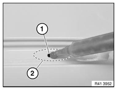
Fig. 267: Filling Roof Channel Hole Using Adhesive
Apply adhesive bead (1) to the underside of the clip.
In so doing, fill channel of clip with adhesive.
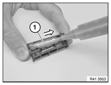
Fig. 268: Applying Adhesive Bead To Underside Of Clip
Move clip (1) into position and secure by hand.
If the adhesive is not already emerging evenly through the channel, apply additional adhesive from above.
Adhesive bead (2) must be below the clip height.
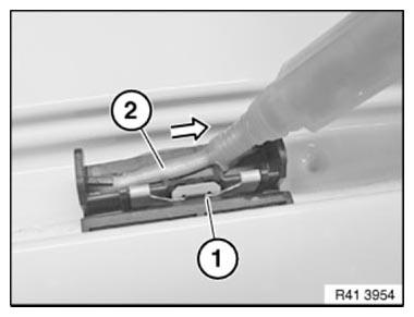
Fig. 269: Moving Clip
Secure clip with adhesive tape (1), approx. 150 mm long.
Apply adhesive tape in direction of travel.
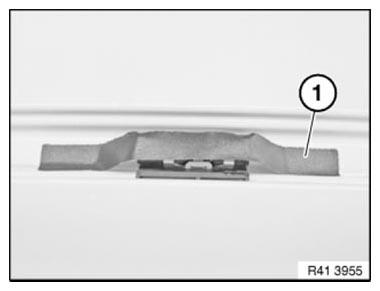
Fig. 270: Securing Clip With Adhesive Tape
4.0 Hardening period
- Adhesive tape can be removed after approx. 10 mins.
- Earliest possible load capability, e.g. fitting of roof strip, after 30 minutes.
READ NEXT:
 Replace Roof Outer Skin
Read contents of BODY, GENERAL.
STRIP DOWN VEHICLE
NOTE: Observe new procedure for bonding and riveting (REPAIR STAGE 2).
Following parts are required:
Roof outer skin
Additional required parts (no
Replacing Roof Outer Skin (Version With Slide/tilt Sunroof)
Read contents of BODY, GENERAL.
STRIP DOWN VEHICLE
NOTE: Observe new procedure for bonding and riveting (REPAIR STAGE 2).
Following parts are required:
Roof outer skin
Additional required parts (n
SEE MORE:
Removing And Installing/Replacing Left Inlet Camshaft (N63)
Necessary preliminary work
(cylinder bank 5 to 8)
IMPORTANT: The intake camshaft must first be rotated in such a way that
the camshaft is
free from tension when the bearing caps are released (risk of damage).
Remove LEFT CYLINDER HEAD COVER.
Check TIMING.
Remove LEFT INLET ADJUSTMENT UNIT.
IMP
Operating Fluids
1.0 GENERAL INFORMATION
Brake fluid, (glycol-based) as used in BMW brake systems, must conform with
the following requirements:
High boiling point
Good low temperature resistance
Low compressibility
Corrosion inhibition for all metal parts inside of brake system
Compatibility with all rubber
