BMW 7 Series: Removing And Installing (Replacing) Head Unit
IMPORTANT: Risk of damage! There is a hard disk installed in the head unit.
Carry out mechanical work on the head unit and adjacent components with care.
Avoid subjecting the head unit to vibration/shocks.
IMPORTANT: Read and comply with NOTES on protection against electrostatic damage (ESD protection).
NOTE: Comply with notes and instructions on HANDLING OPTICAL FIBRES.
Necessary preliminary work:
- Remove RADIO AND IHKA CONTROLS.
- Disconnect NEGATIVE BATTERY CABLE (F03: disconnect both negative battery cables).
NOTE: Picture for example purposes only!
Unfasten screws (2).
Pull head unit (3) out of guide.
Installation note: Make sure head unit (3) is correctly seated in guide lugs (1).
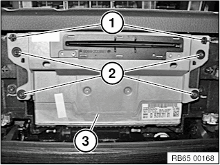
Fig. 6: Identifying Head Unit, Screws, And Guide Lugs
Set the protective nonwoven material (1) aside as shown.
Unlock plug connections.(2) and disconnect.
Remove head unit (3).
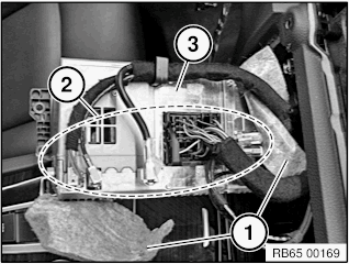
Fig. 7: Identifying Head Unit And Connections
Only for US models with satellite radio: When replacing the head unit, additional work is required!
- Refer to REMOVING AND INSTALLING/REPLACING SATELLITE TUNER (ONLY FOR US MODELS STARTING AT 09/2009).
Replacement: Carry out VEHICLE PROGRAMMING AND ENCODING.
OVERVIEW OF AUDIO COMPONENTS
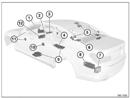
Fig. 8: Overview Of Audio Components
- Speaker (in dashboard)
- Central Information Display (CID)
- DVD changer
- DVD player, rear console
- Aerial diversity
- Speaker (in storage shelf)
- Satellite tuner
- Amplifier
- Central bass speaker
- Speaker (door, rear)
- Speaker (door, front)
- Car Information Computer (CIC)
REMOVING AND INSTALLING (REPLACING) AMPLIFIER (TOP HIFI SYSTEM)
IMPORTANT: Read and comply with NOTES on protection against electrostatic discharge (ESD protection).
NOTE: Comply with notes and instructions on HANDLING OPTICAL FIBRES.
Necessary preliminary work
- Clamp off NEGATIVE BATTERY CABLE.
- Remove LUGGAGE COMPARTMENT WHEEL ARCH PANEL ON LEFT.
Release screw (1).
Remove amplifier (2) in direction of arrow from holder (3).
Unlock plug connections and disconnect.
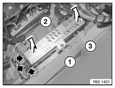
Fig. 9: Identifying Screw, Amplifier And Holder
NOTE: Until 09/2009 a Top Hifi amplifier with a different pin assignment is installed!
Install cable jumper consisting of socket (1) (BMW Parts Service 6901844) and wire jumper (2) in connector (3).
Create wire jumper (2) from wire (cross-section 0.75 mm2 ) and two stops (BMW Parts Service 1393724). Then connect pins 1 and 2 in socket (1) with wire jumper (2).
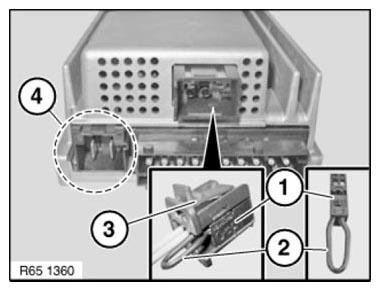
Fig. 10: Identifying Cable Jumper, Wire Jumper, Connector And Connector
Chamber
NOTE: Connector chamber (4) is not included in current version and remains unused in new replacement Top HiFi amplifier!
NOTE: Picture for example purposes.
Installation note: Tabs (1) must be correctly slid into guide (2).
Check that amplifier (3) is securely seated.
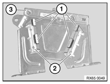
Fig. 11: Identifying Tabs, Guide And Amplifier
Replacement
Carry out VEHICLE PROGRAMMING AND ENCODING.
READ NEXT:
 Removing And Installing/Renewing Central Bass Speaker-Driver's Side- (Under
Front Seat)
Removing And Installing/Renewing Central Bass Speaker-Driver's Side- (Under
Front Seat)
Necessary preliminary tasks
Remove FRONT SEAT, DRIVER'S SIDE
Remove PANEL FOR DOOR PILLAR.
Pull trim (1) in direction of arrow towards rear and lift out.
Fig. 12: Identifying Trim
Release plastic
Removing And Installing/Replacing Amplifier
IMPORTANT: Read and comply with NOTES on protection against electrostatic
damage (ESD
protection).
NOTE: Comply with notes and instructions on NOTES ON HANDLING OPTICAL
FIBRES.
Necessary preliminary
SEE MORE:
Providing assistance
Hazard warning flashers
The button is located in the center console.
Breakdown assistance
BMW Roadside Assistance
Via iDrive:
"APPS"
"Installed apps"
"BMW Assist"
If necessary, "BMW Roadside Assistance"
A voice connection is established.
ConnectedDrive
Concierge service
The BMW Assist Conc
Checking Camshaft Timing On Left Side (N63)
Notes
IMPORTANT: The timing can only be checked with special tool 11 9 900.
The timing may be misinterpreted if it is checked without special tool 11 9 900.
Cylinders 5-8:
Necessary preliminary work
Remove left CYLINDER HEAD COVER
Remove FAN COWL with electric fan
Remove BELT PULLEY for air con
