BMW 7 Series: Cover For Frame Side Member (Part Replacement Between A And B Pillar)
Observe procedure for REPAIR STAGE 3.
Read contents of BODY, GENERAL.
Following new body parts are required:
- B-pillar with entrance
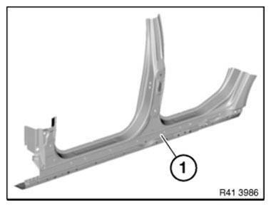
Fig. 251: Identifying B-Pillar With Entrance
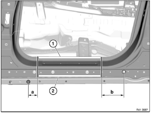
Fig. 252: Identifying Welded Connections Areas
Mark severance cuts in accordance with specified measurements and cut.
IMPORTANT: Cut outer panel only for following severance cuts.
Measurement a = approx. 70 mm behind hole dia. 25 mm.
Dimension b = approx. 180 mm in front of 25 mm hole.
Open welded connections in areas (1) and (2).
Installation note: Mark new part in accordance with severance cuts on vehicle and cut.
Open welded connections of new part to suit the vehicle.
Weld in REINFORCEMENT PLATES at all severance cuts.
Set repair welding spots in area (1) on existing welding spots on vehicle. This is necessary because the adhesive between the spot flanges acts as an insulator.
Replacing Engine Support/Front Left Side Frame Connection (Front Left Wheel Arch Removed)
Observe procedure for REPAIR STAGE 3.
Read contents of BODY, GENERAL.
To remove engine support side frame connection
Following new body parts are required:
- Connection, wheel arch/entrance
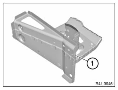
Fig. 253: Identifying Connection, Wheel Arch/Entrance
Open welded connections in areas (1).
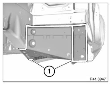
Fig. 254: Identifying Welded Connections Areas
View from below: Open welded connections in areas (1).
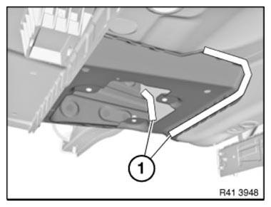
Fig. 255: Identifying Welded Connections Areas
View from below: Open welded connections in areas (1).
Remove wheel arch/entrance connection.
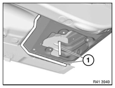
Fig. 256: Identifying Welded Connections Areas
New part preparation
Open welded connections in area (1).
Remove metal section (2).
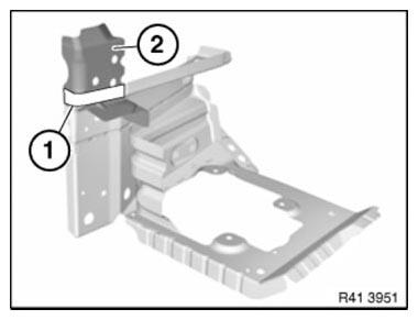
Fig. 257: Identifying Welded Connections Area And Metal Section
To install engine support side frame connection
Install and weld new parts.
READ NEXT:
 Replacing Front Left Door Post (Front Side Panel Removed)
Procedure OBSERVE repair stage 3! Read contents of BODY, GENERAL.
Spot-weld bonding is used on this vehicle. Observe specific procedure.
Place vehicle on straightening bench.
Following new body par
Repairing Clips For Roof Strip
The following instructions describe the permanent repair gluing of clips
which were originally secured with T-pins.
The repair gluing at the same time protects the area of the torn-off T-pin
perman
SEE MORE:
Introduction
Refinements in Detail
The longitudinal dynamics systems described in this document comprise the
following:
Dynamic stability control (DSC) and
Electromechanical parking brake (EMF)
Both DSC and EMF are standard equipment on all F01/F02 models. Thus BMW has
consistently continued the
standards
Removing And Installing/Renewing USB Interface Connecting Socket
Necessary preliminary work:
Remove SWITCH FOR FRONT PASSENGER AIRBAG DEACTIVATION
NOTE: Open glove box
Disconnect plug connection (1).
Unlock retaining clips (2) on left/right.
Press out USB interface connecting socket (3) in direction of arrow.
Installation note:
Retaining clips (2) must not
