BMW 7 Series: Cellular Telephone
REMOVING AND INSTALLING (REPLACING) TELEMATIC COMMUNICATION BOX
IMPORTANT: Read and comply with notes on protection against electrical damage (ESD PROTECTION).
Comply with notes and instructions on HANDLING OPTICAL FIBRES.
Necessary preliminary work:
- Clamp off BATTERY NEGATIVE LEAD.
- Remove LEFT LUGGAGE COMPARTMENT WHEEL ARCH PANEL.
- For F10: Partially remove luggage compartment wheel arch trim on left.
Unscrew nuts (1).
Tightening torque: 6, 0 Nm
Release screw (2).
Tightening torque: 6, 0 Nm
Remove holder and Telematic Communication Box (3) in direction of arrow.
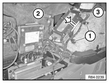
Fig. 1: Removing TCU Holder
NOTE: Graphic similar
Unlock and disconnect all plug connections in area (1).
Release all nuts (2).
Tightening torque: 3, 3 Nm Remove Telematic Communication Box (3) from holder.
Installation note: Note color coding of plug connection.
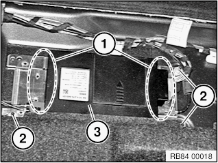
Fig. 2: Identifying Telematic Communication Box, Connectors, And Nuts
Replacement:
- Carry out VEHICLE PROGRAMMING/ENCODING.
REMOVING AND INSTALLING (REPLACING) USB HUB
IMPORTANT: Read and comply with notes on protection against electrostatic damage (ESD PROTECTION).
Necessary preliminary work
- Remove TRIM PANEL FOR DOOR PILLAR, (BOTTOM) LEFT
Disconnect plug connection (1).
Release screws (2) and remove USB hub (3).
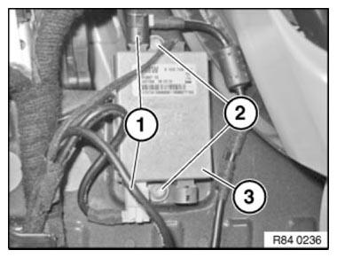
Fig. 3: Identifying Plug Connection With USB Hub And Screws
Replacement:
Carry out VEHICLE PROGRAMMING/ENCODING.
REMOVING AND INSTALLING/REPLACING BASE PLATE
Necessary preliminary tasks
- Remove CENTRE ARMREST STORAGE COMPARTMENT
NOTE: Unlock base plate (1) and fold upwards.
Unfasten screws (2).
Feed out base plate (1) and remove.
Installation: Ensure correct cable routing in base plate (1).
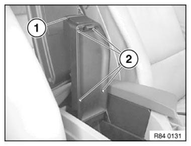
Fig. 4: Identifying Base Plate With Screws
REMOVING AND INSTALLING/REPLACING BASE PLATE (IN CENTER ARMREST AT REAR)
Necessary preliminary tasks
- Fold down center armrest
- Open upper armrest section
Slide in special tool 00 9 341 as pictured and release catch.
Remove base plate (1) in direction of arrow.
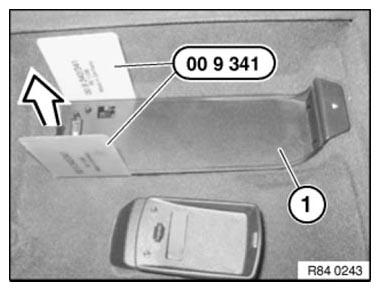
Fig. 5: Removing Base Plate
Unlock plug connections (1) and disconnect, remove base plate.
Installation: Catches (2) must not be damaged.
Ensure correct routing of cables.
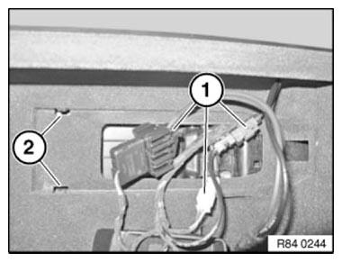
Fig. 6: Identifying Plug Connections And Catches
READ NEXT:
 Transceiver, Handset+Support, Card Reader
REMOVING AND INSTALLING/REPLACING TELEMATIC CONTROL UNIT (TCU)
(SA633/SA639)
IMPORTANT: Read and comply with notes on protection against electrical
damage (ESD
PROTECTION).
NOTE: Comply with notes an
Handheld Computer
REMOVING AND INSTALLING (REPLACING) HANDSFREE CHARGING
ELECTRONICS (HIGH)
Operation is described in:
REMOVING AND INSTALLING (REPLACING) HANDSFREE CHARGING ELECTRONICS
(OPTIONAL EXTRA SA644)
Replaceme
Hands-Free System, Microphone, Speaker
REMOVING AND INSTALLING/REPLACING HANDS-FREE MICROPHONE, DRIVER'S
SIDE
Lever out microphone cover (1) at front in direction of arrow.
Disconnect plug connection underneath and remove microphone cover
SEE MORE:
Electrical Steering Column Adjustment
System Circuit Diagram for Electrical Steering Column Adjustment
Fig. 140: Electrical Steering Column Adjustment System Circuit Diagram
COMPONENTS DESCRIPTION CHART
Central gateway module ZGM
Front distribution box
Distribution box in luggage compartment
Steering column switch cluster
Steerin
Service Information
Calibration of the Drivers/front-Passenger Seat in the US Version
The position of the driver's seat in the longitudinal direction can become
implausible in the course of that seat's
life. This can be caused by repeatedly moving the seat forward and back in the
longitudinal direction.
These moveme
