BMW 7 Series: Stripping Operations - Replacing Front Left Wheel Arch
NOTE: Owing to the different engine variants and equipment specifications, not all the components are taken into consideration.
The following list basically represents the removal sequence.
- Disconnect battery earth lead (job number: 61 20 900)
- Remove bumper trim (job number: 51 11 156
- Remove bumper support (job number: 51 11 050)
- Remove headlight (job number: 63 12 010)
- Remove radiator (job number: 17 11 000)
- Remove A/C system condenser (job number: 64 53 550)
- Remove and install charge air cooler (job number: 17 51 000)
- Remove hydraulic steering cooling coil (job number: 17 11 370)
- Remove intake silencer housing (job number: 41 35 111)
- Remove coolant expansion tank (job number: 17 11 100)
- Remove wheel arch cover (front section) (job number: 51 71 038)
- Remove wheel arch cover (rear section) (job number: 51 71 039)
- Front axle complete with engine and transmission (job number: 31 10 001)
- Engine compartment lid seal locator (job number 51 76 035).
- Remove engine compartment lid (job number 41 61 000)
- Remove engine compartment lid hinge (job number: 41 61 050)
- Remove left side wall (job number: 41 35 050)
- Remove top left wishbone (job number: 31 12 002)
- Remove left suspension brace (job number: 51 71 345)
- Remove bulkhead sound insulation
- Remove brake booster (job number: 34 33 000)
- Remove/detach hydraulic lines for power steering pump.
- Detach coolant hoses
- Detach fuel lines
- Release left wiring harness
- Partially release/remove thermal protection
STRIPPING OPERATIONS - REPLACING FRONT RIGHT WHEEL ARCH
NOTE: Owing to the different engine variants and equipment specifications, not all the components are taken into consideration.
The following list basically represents the removal sequence.
- Disconnect battery earth lead (job number: 61 20 900)
- Remove bumper trim (job number: 51 11 156)
- Remove bumper support (job number: 51 11 050)
- Remove headlight (job number: 63 12 010)
- Remove radiator (job number: 17 11 000)
- Remove A/C system condenser (job number: 64 53 550)
- Remove and install charge air cooler (job number: 17 51 000)
- Remove hydraulic steering cooling coil (job number: 17 11 370)
- Remove intake silencer housing (job number: 41 35 111)
- Remove coolant expansion tank (job number: 17 11 100)
- Remove wheel arch cover (front section) (job number: 51 71 038)
- Remove wheel arch cover (rear section) (job number: 51 71 039)
- Front axle complete with engine and transmission (job number: 31 10 001)
- Remove engine compartment lid seal mounting (job number: 51 76 035)
- Remove engine compartment lid (job number 41 61 000)
- Remove engine compartment lid hinge on right (job number: 41 61050)
- Remove right side wall (job number: 41 35 055)
- Remove top right wishbone (job number: 31 12 003)
- Remove right suspension cross-brace (job number: 51 71 346)
- Remove bulkhead sound insulation
- Remove heating A/C system blower (job number: 64 11 213
- Remove air conditioning refrigerant lines.
- Release right wiring harness
- Partially release/remove thermal protection
Release grommet (1) from fan housing and lay wiring harness (2) to one side.
Installation note: The sealant between grommet (1) and fan housing must be replaced!
Make sure rubber grommet (1) is correctly seated. (watertightness).
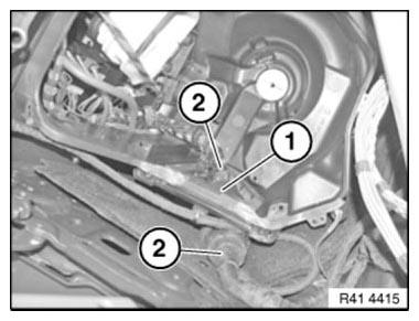
Fig. 250: Identifying Wiring Harness And Rubber Grommet
VEHICLE IDENTIFICATION NUMBER, GENERAL
In the event of repair 2 procedures are used, depending on the vehicle. Refer to the vehicle-specific repair instructions for the correct procedure.
1. General notes for stamped vehicle identification numbers
The vehicle identification number is stamped with a special tool. There are different special tool numbers and stamping procedures for the various vehicles. Refer to the relevant repair instructions.
In repair work, the vehicle identification number is always stamped into a replacement vehicle identification number surface. The replacement surface is usually situated under the original VIN surface.
The IGEF number (bodyshell number) is omitted when the wheel arch is replaced.
In the event of component or body replacement by the BMW garages/workshops, clearly delimit the vehicle identification number at front and rear by stamping a + in place of the BMW badge.
If a VIN is stamped into the replacement surface in addition to the original VIN (e.g. if the original VIN has been tampered with), the following applies: The original VIN must be crossed out. To do so, stamp the letter I from the punch digits lengthways through the original VIN.
IMPORTANT: Do not use an angle grinder in conjunction with a cutting disk!
The protective film used as standard is omitted after the VIN has been manually stamped in. Paint area in accordance with BMW Painting Handbook. Ensure that layer thicknesses are small.
Observe national/country-specific regulations.
2. General notes for embossed vehicle identification numbers
This procedure is used on all newly launching model series from model year 09/2008 (exception X1).
For the repair new parts with an embossed vehicle identification number can as a rule be ordered from the BMW Parts Department. If this is not possible, observe country-specific regulations.
The IGEF number (bodyshell number) is omitted when the wheel arch is replaced.
If a VIN is embossed into the replacement surface in addition to the original VIN (e.g. if the original VIN has been tampered with), the following applies: The vehicle-specific repair instructions describe the procedure.
The protective film used as standard is omitted after the VIN has been embossed. Paint area in accordance with BMW Painting Handbook. Ensure that layer thicknesses are small.
Observe national/country-specific regulations.
READ NEXT:
 Cover For Frame Side Member (Part Replacement Between A And B
Pillar)
Cover For Frame Side Member (Part Replacement Between A And B
Pillar)
Observe procedure for REPAIR STAGE 3.
Read contents of BODY, GENERAL.
Following new body parts are required:
B-pillar with entrance
Fig. 251: Identifying B-Pillar With Entrance
Fig. 252: Identi
Replacing Front Left Door Post (Front Side Panel Removed)
Procedure OBSERVE repair stage 3! Read contents of BODY, GENERAL.
Spot-weld bonding is used on this vehicle. Observe specific procedure.
Place vehicle on straightening bench.
Following new body par
SEE MORE:
General information
Electronic control devices are installed in the vehicle.
Electronic control units process data they
receive from vehicle sensors, self-generate or
exchange with each other. Some control units
are necessary for the vehicle to function safely or
provide assistance during driving, for instance
driver
System Components
Park Distance Control
The Park Distance Control of the F01/F02 is identifiable by the five
ultrasonic sensors on the front bumper. The
fifth sensor enables a high level of reliability in obstacle recognition to be
achieved despite the large front end
of the F01.
Fig. 136: F01/F02 Front Bumper Wit
